Categories
Meshtastic Project Ideas Raspberry Pi Software Development

Meshtastic with Raspberry Pi (Serial) – Part IV

In this part of the Meshtastic with Raspberry Pi (Serial) series, we will be writing some code to test the connection, then adding to our code to send sample data. When sending data, we will format the message to allow us to reject data if it is not formatted correctly and do some simple error detection.

A good resource, which will be used to write this code may be found on the “Raspberry Pi UART Communication using Python and C” page on the ElectronicWings site.

Preparation

You need to start off by editing the cmdline.txt file to remove the console=serial0,115400 argument and value. If you don’t do this, you will see errors similar to ‘device reports readiness to read but returned no data’. More information and background is available at https://raspberrypi.stackexchange.com/questions/111817/serial-serialutil-serialexception-device-reports-readiness-to-read-but-returned

On the Raspberry Pi, open a terminal window or use PuTTY to run the following command.
sudo nano /boot/cmdline.txt

Initial cmdline.txt opened in nano editor

Comment out or delete the “console=serial0,115400” in the line.

Modified cmdline.txt opened in nano editor

Once the cmdline.txt has been modified, restart the Raspberry Pi.

NOTES: If the console=serial0,115400 is missing, you skipped enabling the serial port from the raspi-config tool. Look back at the earlier posts in this series for instructions on how to enable the serial port. It is also possible that the baud rate in the command is something other than 115400 so you may see a different baud rate, which is fine, but you will need to remove that argument from the file.

Test Program

Now that the serial port is properly configured, we can write a simple program and test the T-Beam connection to the Raspberry Pi. On both Raspberry Pi boards, create a uart.py file with the following code.

'''
UART communication on Raspberry Pi using Python
http://www.electronicwings.com
'''
import serial
from time import sleep

ser = serial.Serial ("/dev/ttyS0", 38400)    #Open port with baud rate
while True:
    raw_data = ser.read()              #read serial port
    sleep(0.03)
    if raw_data:
        data_len = ser.inWaiting()
        raw_data += ser.read(data_len)              #read serial port
        received_data = str(raw_data, "utf-8")
        print (received_data)                   #print received data

The code will listen for data on the serial port and will print the received data in the terminal window. Run the code on both Raspberry Pi boards by typing the following command.
sudo python uart.py

On the Android device, open the Meshtastic application and type a message and press the send button.

Meshtastic App with Phoebe sending the message "Hello Rachel"

The message will be displayed in the terminal window of the receiving Raspberry Pi device.

Message "Hello Rachel" received in the terminal window

Sample code sending and receiving data

Before using the following example, it is suggested to change the serial configuration to “Simple” and creating an additional channel named “serial”. Screenshots were taken of the Meshtastic application and placed into a Google Album. Refer to the album if you have any questions regarding what configuration values were used for this example.

The sample code will send CPU Temperature data twice per minute. Below are a few notes/requirements.

  • The data will be sent as JSON.
  • The data will be contained in a Python Dictionary with string values for the keys.
    Sample keys:
    • t: Time in UTC ISO 8601 format without milliseconds
    • nam: The host name of the Raspberry Pi
    • cput: CPU Temperature in degrees Celsius
  • Float values will be sent as formatted strings with the precession required for the application. As an example, temperature will be sent with two decimal values.
  • The total length of the message shall not exceed 200 bytes. In practice, it should be kept well below 200 bytes. This requires that the keys for the key value pairs to be kept short.

Example Code:

The following example code was written to meet the above requirements.

'''
- References -
--------------
ISO 8601
    https://pynative.com/python-iso-8601-datetime/
UART communication on Raspberry Pi using Pyhton
    http://www.electronicwings.com
'''

import serial
import time
from datetime import datetime, timezone
import re
import socket
import json

def get_temp():
    with open('/sys/class/thermal/thermal_zone0/temp', 'r') as infile:
        return float(infile.read()) * 1e-3

# Open port with baud rate
ser = serial.Serial("/dev/ttyS0", 38400)
# Set the start time in the past so that the first data point will be sent at the startF
start = time.time() - 600
# Create a variable for the received data.
received_data = ""
# Flag for knowning if the error for T-Beam being disconnected has been displayed
no_serial = False

try:
    while True:
        data_len = 0
        data_len = ser.in_waiting
        utc_dt = datetime.now(timezone.utc).replace(microsecond=0)

        if data_len > 0:
            raw_data = ser.read(data_len)  # read serial port
            try:
                received_data += str(raw_data, "utf-8")
                x = re.search("\{.*\}", received_data)
                if x:
                    # PuTTY changes tab characters to spaces so we will use the pipe symbol
                    # print(F"{utc_dt.isoformat()}\tRECV\t{x[0]}")
                    print(F"{utc_dt.isoformat()}|RECV|{x[0]}")
                    received_data = ""
                if no_serial:
                    no_serial = False
            except UnicodeDecodeError:
                received_data = ""
                if not no_serial:
                    print("ERROR: The serial connection may be down")
                    no_serial = True

        if time.time() - start > 30:
            start = time.time()
            temp = get_temp()
            dat = {
                "t": utc_dt.isoformat(),
                "nam": socket.gethostname(),
                "cput": F"{temp:0.2f}",
            }
            if len(json.dumps(dat)) < 200:
                ser.write(bytes(json.dumps(dat), "utf-8"))
                # PuTTY changes tab characters to spaces so we will use the pipe symbol
                # print(F"{utc_dt.isoformat()}\tSENT\t{json.dumps(dat)}")
                print(F"{utc_dt.isoformat()}|SENT|{json.dumps(dat)}")
            else:
                print(
                    F"ERROR: Data length is greater than 200 bytes (length={len(json.dumps(dat))})")

except KeyboardInterrupt:
    print("\r\nExiting")
# finally:
#   GPIO.cleanup()

Below is the output from both Raspberry Pi boards running the code with the same T-Beam Meshtastic settings.

Two PuTTY windows side-by-side with each connected to separate Raspberry Pi boards

An Excel workbook was put together to check the delay from transmit and receive as well as identifying packets being received out of order. Previous runs with slightly different code did contain out of order packets so it should not be assumed that packets will be received in order. Below is the Check.xlsx file that you may download.

Below are some statistics from the Check.xlsx Excel Workbook with data produced from 27 minutes runtime of the sample code.

  • pi-sensor01
    • Receive Delay (hh:mm:ss)
      • Min: 00:00:07
      • Max: 00:04:12
      • Average: 00:01:28
      • Median: 00:00:57
    • Data Received out of order: 0
    • Data Points
      • Total: 104
      • Sent: 56
      • Received: 48
    • Sent Packets Received by pi-sensor01:
      • Received: 55
      • Not Received: 1
      • Percent of Packets Received: 98.21%
  • pi-sensor02
    • Receive Delay (hh:mm:ss)
      • Min: 00:00:07
      • Max: 00:01:35
      • Average: 00:00:23
      • Median: 00:00:15
    • Data Received out of order: 1
    • Data Points
      • Total: 111
      • Sent: 56
      • Received: 55
    • Sent Packets Received by pi-sensor01:
      • Received: 48
      • Not Received: 8
      • Percent of Packets Received: 85.71%

Going Further

This is the end of this series at least for now. It was put together to provide some information with one way to send data between two Raspberry Pi devices using serial communications. There are other ways to send data using the serial port. One of the more interesting ways may be using the PROTO mode for the Meshtastic serial port. It looks like using the PROTO mode may allow for the code to setup and configure the Meshtastic device. If that is the case, it may provide much more control and standardization across connections. (Meshtastic Serial Port Configuration)

Another area to look into is how to improve the successful delivery of messages in a timely manor. It may be sending messages every 30 seconds was too fast and flooded the available channels. It may also be possible that the store and forward setting was misunderstood and caused message flooding on the channel. The devices may have been too close together to provide reliable communications. All of these things and others could be looked into to see if it is possible to create more reliable communications.

Categories
Meshtastic Project Ideas Raspberry Pi Software Development

Meshtastic with Raspberry Pi (Serial) – Part III

In this part of the Meshtastic with Raspberry Pi (Serial) series, we will be installing Meshtastic to the LilyGo T-Beam devices. We will then create a Meshtastic Channel on one LilyGo T-Beam and replicate the channel to the other LilyGo T-Beam. We will then wire the Raspberry Pi and LilyGo T-Beam devices.

Install Meshtastic Firmware on the LilyGo T-Beam devices

Visit the Meshtastic Web Installer at https://flasher.meshtastic.org/. Select the following options:

  • Device: Tbeam
  • Firmware Version: Select the latest version.
    NOTE: May want to install latest beta version if you want the most stable version available.
  • Update or reinstall: Either option is fine. A reinstall may wipe out any settings that you have configured on the device but may be the best option for the first installation.
Meshtastic Web Installer

Click the “CONNECT” button

Select the serial port that the T-Beam is connected to. If you are uncertain, you may open the Windows Device Manager and look at Ports (COM & LPT), then look for “USB-Enhanced-SERIAL CH9102” or similar device to find the serial port.

Meshtastic Web Installer - Select COM Port

Click “INSTALL TBEAM”

Meshtastic Web Installer - Install TBeam

Click “INSTALL”

Meshtastic Web Installer - Install

You will see the progress as it installs the firmware.

Meshtastic Web Installer - Installing
Meshtastic Web Installer - Installing 38%

When the installation is complete, click “NEXT”

Meshtastic Web Installer - Installation Complete

You may then click the X in the device dashboard to close the dashboard.

Meshtastic Web Installer - Close Device Dashboard

Repeat the steps for the other T-Beam, then close the browser.

Configure T-Beam and Create Channel

Using a mobile phone, tablet, or PC, open the Meshtastic App or Web Client. The following examples will show the Web Client and Android App.

Web Browser on a PC

It is best to use the Android application to configure the T-Beam device. The instructions provided here for the Web Browser are incomplete as I could not determine how to set some of the options that I know are available in the Android Application. These instructions are provided to demonstrate how to access the configuration from the web browser.

With the LilyGo T-Beam connected to the PC, open a browser and navigate to https://client.meshtastic.org/. Click the “New Connection” button.

Web configuration main page

The “Connect New Device” dialog is shown. Click the “New device” button.

Web configuration - Select device

Select the T-Beam device from the list of devices and click the “Connect” button.

Web configuration - Connect New Device Screen with new device listed

Click the device from the device list.

Web configuration - Connect New Device Screen - Close button

The selected device will turn gray to show that it is selected. Click the X in the top right corner of the “Connect New Device” dialog to close the dialog box.

Web configuration - LoRa Configuration

Android App

If the Meshtastic application is not already installed, go to the Play Store and search for an install the Meshtastic App.

Play Store - Meshtastic App

Open the Meshtastic Application and click the gear icon in the top toolbar on the right, then click the “+” in the lower right corner to add a new Meshtastic device.

Meshtastic Devices Screen

On the T-Beam device, look for the device name on the LCD screen.

Meshtastic T-Beam LCD Screen

In the Meshtastic App, select the device name that matches the name on the T-Beam LCD Screen, in the list of available devices.

Meshtastic App - Device Link Selection List

The T-Beam device will display a Bluetooth pin on the LCD Screen.

Meshtastic T-Beam LCD Screen with Bluetooth Pin

Enter the Pin in the Bluetooth pairing request screen and click “OK”.

Meshtastic App - Enter Bluetooth Pin

Next, we need to set the region by clicking on the region dropdown.
NOTE: Make certain that the correct device is selected.

Open region dropdown list

Select your region from the list. My region is “US”, so that is what I selected.

Select region

The selected region will be displayed in the application and the T-Beam device will reboot.

Meshtastic App - Region Set

Once the device reboots, you may enter a name if you like. Do not move off this screen right away or the name may not stick. You may find that you need to reenter the name a few times before it is saved.

Meshtastic App - Change Name

Click on the hamburger menu in the upper right corner and select “Radio configuration”.

Meshtastic App - Hamburger Menu

Click on “Serial” from the “Radio configuration” menu.

Meshtastic App - Radio configuration menu

Enter the settings for the Serial Port, then click the “Send” button.

  • Serial enabled: Turn on
  • RX: Pin 13
  • TX: Pin 14
  • Serial baud rate: Selected 38400 baud but may select different rate. Make certain this matches when writing code on the Raspberry Pi.
  • Serial mode: TEXTMSG
Meshtastic App - Serial Settings

If you want a private channel, setup the channel on one device, then scan the QR Code on the other devices in the Mesh. I will not go over setting up a channel. For more information on setting up a channel, go to Meshtastic’s Channel Configuration page.

Wire Everything Up

The connection between the Raspberry Pi and the T-Beam device only requires three wires. A wire for the ground and two for the serial connection. The serial connection will cross the transmit (TX) and receive (RX) wires so that the TX from the Raspberry Pi is connected to the T-Beam RX and the Raspberry Pi RX will connect to the T-Beam TX. Below is a diagram showing these connections.
Wiring diagram for Raspberry Pi board connected to LilyGo T-Beam device
Categories
Meshtastic Project Ideas Raspberry Pi Software Development

Meshtastic with Raspberry Pi (Serial) – Part II

In Part I, we installed the Raspberry Pi OS and connected to the Raspberry Pi using PuTTY and VNC from another PC. In Part II, we will install Visual Code on the Raspberry Pi to allow us to code directly on the Raspberry Pi using a modern IDE.

It is not required to install Visual Studio Code. There are several options for writing programs and running them on the Raspberry Pi. It is possible to simply use the Text Editor on the desktop, Nano or VI from the terminal, or use an editor on the PC and transfer files using WinSCP.

Installing Visual Studio Code

The first thing to note is that the Chromium web browser is not going to work well on older Raspberry Pi boards. I am using a Raspberry Pi 3, so it is necessary to open a terminal and run the following command to launch the Dillo web browser:
dillo

Once the browser is open, navigate to https://code.visualstudio.com/download.

Dillo web browser showing the Visual Studio Code download page

Clicking on the .deb Arm32 link does nothing as the link is using JavaScript to download the correct file. We will need to get the installation package from our PC and move it to the Raspberry Pi.

On the PC, navigate to https://code.visualstudio.com/download and click the .deb Arm32 link to download the installation package. Save it to a known location and remember where you saved it.

Open WinSCP and connect to the Raspberry Pi.

WinSCP Login window

If it is the first time connecting to the Raspberry Pi, you will see a Warning dialog. Click “Yes” to continue.

WinSCP Warning dialog for unknown host

Once connected, in the right pane of the WinSCP application, navigate to the desktop folder on the Raspberry Pi and in the left pane, navigate to the location of Visual Studio Code installation package on your PC. Once the locations have been selected, you may click and drag the installation package from the PC to the Raspberry Pi.

WinSCP window transferring the Visual Studio Code installation package

Once the package has been transferred, switch to VNC Viewer and you will see the file on your desktop.

Raspberry Pi desktop with Visual Studio Code installation package

Right-click on the installation package and select “Package Install” from the context menu.

Package Install on right-click context menu

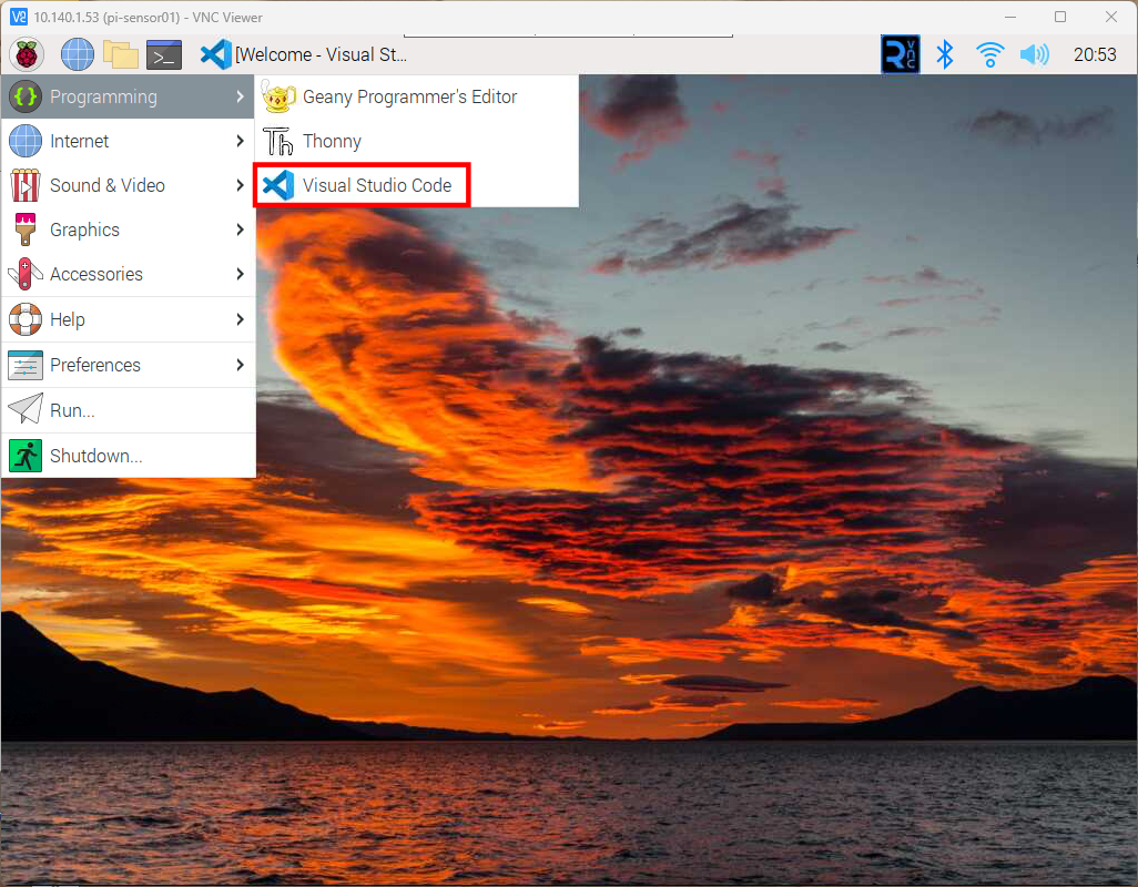
Once the installation completes, you may launch Visual Studio Code from the menu by navigating to Programming > Visual Studio Code.

NOTE: You may delete the Visual Studio Code installer from the desktop if you wish.

Raspberry Pi OS Menu showing Visual Studio Code
Visual Studio first launch

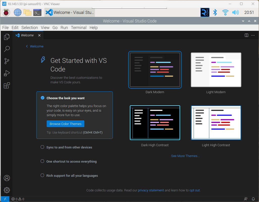
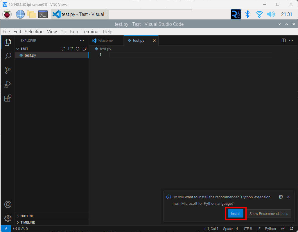
I like to use the Explorer, the top icon on the left toolbar, to open a folder. From there, I may create files and folders for the project. In the screenshot below, I have created a folder named “Test” in my home folder and added a file named “test.py”. Once I created the file, Visual Studio Code recognized that I created a Python file and prompted me to install the Python language extension.

Visual Studio Code with prompt to install Python language extension
Categories
Meshtastic Microcontroller Project Ideas Raspberry Pi Software Development

Meshtastic with Raspberry Pi (Serial) – Part I

In this post, I will step through getting Linux installed on a Raspberry Pi with an overview of different installations, and detailed setup on a headless installation. I will then move into connecting the Raspberry Pi to a LilyGo T-Beam device with Meshtastic Firmware, with the connection to the Raspberry Pi using a Serial Connection. Connecting one or more sensors to the Raspberry Pi, and finally sending that data to another Raspberry Pi connected to a LilyGo T-Beam.

Before Installing Linux on Raspberry Pi

There are several options for installing Linux on the Raspberry Pi. The first question to answer is, which distribution to use? There are several different distributions available for the Raspberry Pi boards. A comprehensive list of distributions available may be found at https://elinux.org/RPi_Distributions. The distribution that I will be using is Raspberry Pi OS by Raspberry Pi.
The next question to answer is do we want a desktop or do we wish to run in headless mode? Installing a desktop is helpful if we wish to use the Raspberry Pi as a regular computer with a nice user interface. Installing a desktop does require more resources but makes the Raspberry Pi more useful if we wish to connect it to a display and keyboard or use VNC from another machine.

A headless mode installation is best if we only need to work from the terminal (command line) and/or we want more resources for running applications to monitor sensors or server up web pages or application program interfaces (API).

The last question to ask is what peripherals and options do we need to have configured? We know we will want the serial interface enabled, since that will be used to communicate to the LilyGo T-Beam devices. Depending on the sensors that we wish to use, we may want to enable the I2C interface.

Another option we will want is to be able to control the Raspberry Pi from another machine as we do not want to connect a monitor, keyboard, and mouse. We will need to enable SSH and VNC to allow control from another machine.

Below is a list of our installation options that we will configure.

  • Distribution: Raspberry Pi OS
  • Mode: Desktop
  • Enable SSH
  • Enable VNC
  • Enable Serial
  • Enable I2C

We have a couple of ways to enable the above configuration but we will configure all of these options from the Raspberry Pi Imager as it makes this relatively easy and quick. The toughest part is determining what the IP Address is of the Raspberry Pi when it boots up.

Required software on the Windows, Linux, or Apple PC

There is some software that we need to have on the PC in order to install the Raspberry Pi OS and control it from the PC.
If the listed software does not support your operating system, look for a similar application for your operating system.

Prepare SD Card for Raspberry Pi

  1. Insert an SD Card in your PC and note the drive letter. Make certain that the SD Card does not have anything that you wish to keep as the card will be wiped, so your information will be gone.
Windows Explorer showing drives with SD Card highlighted
  1. Open the Raspberry Pi OS Imager and click the “Choose OS” button
    In Windows, you will be prompted by the User Account Control (UAC) to continue. Select “Yes”
Raspberry Pi OS Imager window with Choose OS highlighted
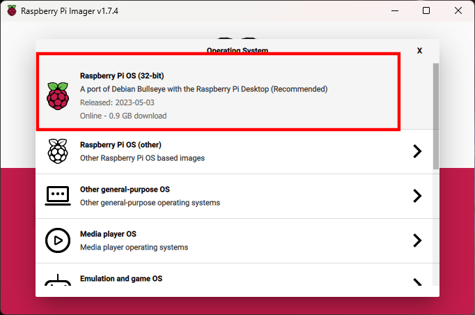
  1. Select “Raspberry Pi OS (32-bit)
Raspberry Pi OS Imager - Operating System Listing
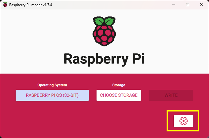
  1. Click the button in the lower right corner, with the gear icon for the advanced settings
Raspberry Pi OS Imager with Advanced Options button highlighted
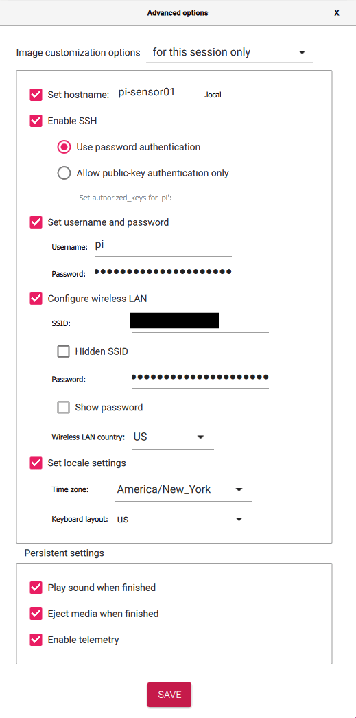
  1. Set the hostname (optional but recommended)
  2. Make certain that “Enable SSH” is checked and “Use password authentication” is selected
  3. Change the password and optionally change the username
  4. Enter the settings for your WiFi connection if not using ethernet
  5. Optionally set time zone and keyboard layout
  6. Once the options have been set, click the “Save” button
Raspberry Pi OS Imager Advanced Options
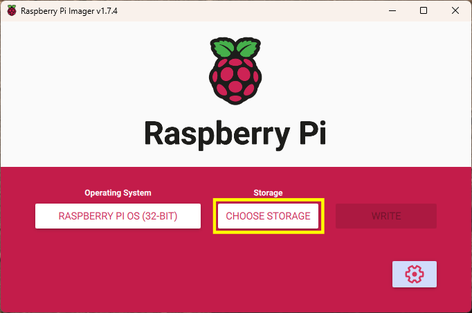
  1. Click the “Choose Storage” button
Raspberry Pi OS Imager window with Choose Storage highlighted
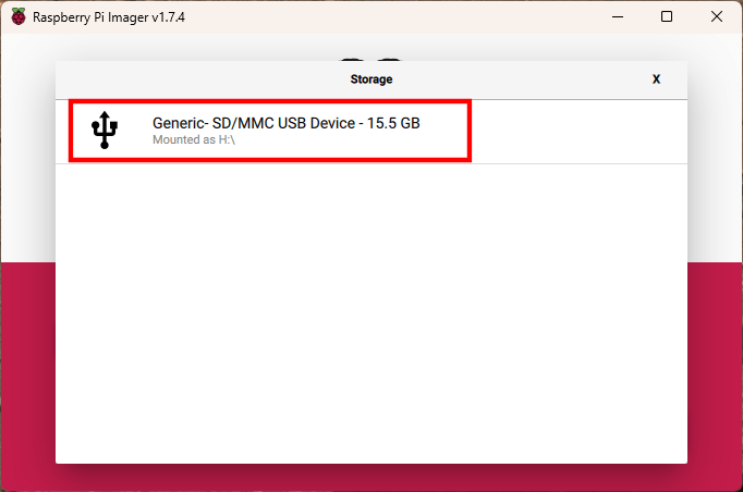
  1. Select the SD Card identified earlier. Make certain that this is the SD Card as all data will be wiped from the selected drive and will not be able to be recovered.
Raspberry Pi OS Imager showing the list of storage devices that may be used
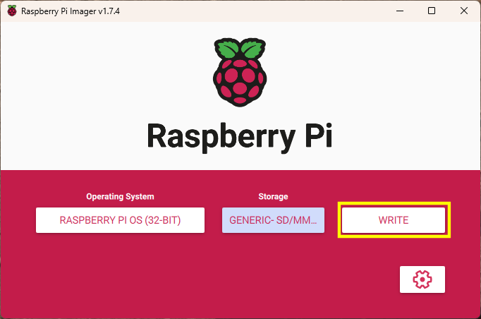
  1. Click the “Write” button to write the OS image to the SD Card
Raspberry Pi OS Imager window with the "Write" button highlighted
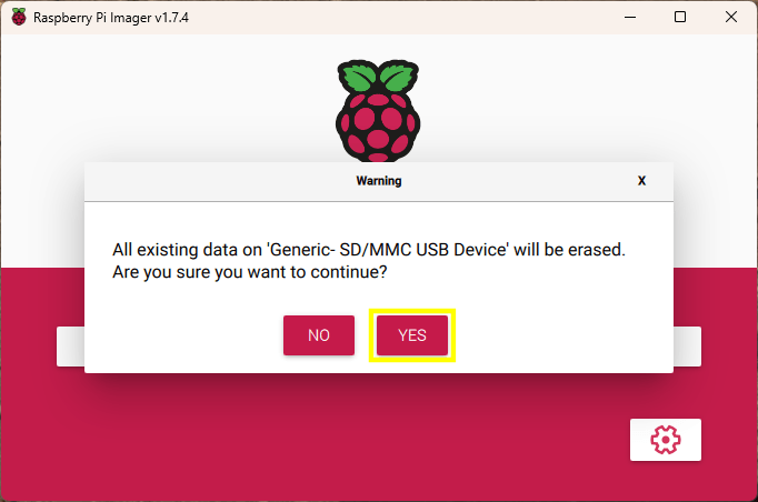
  1. If you are absolutely certain that the correct SD Card has been selected and there is no data on the card that you wish to keep, click the “Yes” button.
Raspberry Pi OS Imager window with the "Yes" button highlighted on confirmation dialog
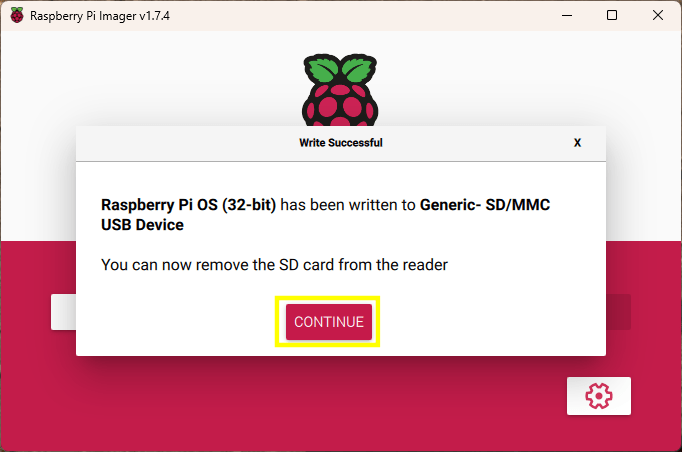
  1. Once the image has been written to the SD Card, you may click the “Continue” button, close the Raspberry Pi OS Imager, and remove the SD Card from the PC, and insert it into the Raspberry Pi.
Raspberry Pi OS Imager  showing the "Write Successful" dialog
  1. Once the SD Card is inserted into the Raspberry Pi, connect power to the Raspberry Pi
  2. After a couple of minutes, open PuTTY on your PC and attempt to connect to the Raspberry Pi using the name provided in the advanced options of the Raspberry Pi OS Imager. In the example, “pi-sensor01.local” was used. In PuTTY, attempt to connect using the hostname provided in the image configuration.
    NOTE: If configuring another Raspberry Pi, do not use the same hostname.
PuTTY Configuration window showing the options for connecing to SSH Session
  1. Click the “Open” button after entering the hostname
  2. You may see a PuTTY Security Alert if it is the first time connecting to the Raspberry Pi. If so, click the “Accept” button.
PuTTY Security Alert window
  1. Once connected, enter the username and password that was entered in the advanced settings fo the the Raspberry Pi OS Imager.
PuTTY window showing successful terminal login
  1. Open the Raspberry Pi Configuration Tool by entering the following command:
    sudo raspi-config
  2. Select option 3, Interface Options, and press the Enter key
Raspberry Pi Configuration Tool with Interface Options selected
  1. Select option I3, VNC, and press the Enter key
Raspberry Pi Configuration Tool with VNC option selected
  1. Select Yes, to enable VNC Server, and press the Enter key
Raspberry Pi Configuration Tool confirmation for enabling VNC
  1. Select OK, and press the Enter key
Raspberry Pi Configuration Tool confirmation for enabling VNC
  1. Repeat the steps above to enable the Serial Port and any other interfaces, such as SPI and I2C that may be needed.
  2. Check if there are any other options that you may want to set or execute. Some useful options are Advanced Options > Expand Filesystem and Update.
  3. When done making changes, select Finish to exit the configuration tool.
  4. If you selected Expand Filesystem, you may want to restart the Raspberry Pi by issuing the following command:
    sudo reboot now

VNC Viewer

Check that we are able to connect the Raspberry Pi Desktop using VNC Viewer.

  1. Open VNC Viewer and connect to the hostname for the Raspberry Pi
VNC Connection Window
  1. If this is the first time you are connecting the Raspberry Pi, you will see an Identity Check dialog. Click the “Continue” button.
VNC Identity Check dialog
  1. Enter the Raspberry Pi username and password, then click the “OK” button.
VNC Viewer prompt for username and password
  1. If everything went correctly, you will be presented with the Raspberry Pi desktop.
Raspberry Pi desktop shown in VNC Viewer
Categories
Arduino Project Ideas Raspberry Pi Pico

Raspberry Pi Pico with Arduino IDE

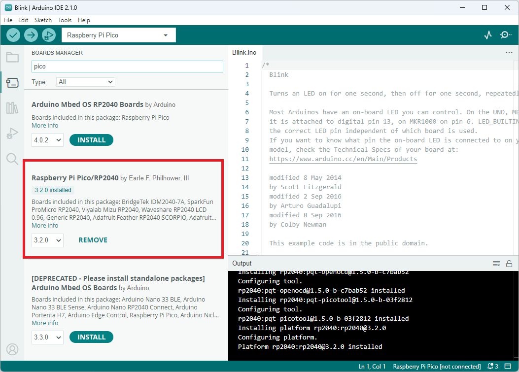
The Raspberry Pi Pico may be programmed in the Arduino IDE. There are three board libraries available but I found that the one written by Earle F. Philhower, III works best. Below are the steps that I took to get the example blink sketch loaded on the Raspberry Pi Pico.

  1. In the Arduino IDE, open the Boards Manager
  2. Type “Pico” in the search box
  3. If the “Arduino Mbed OS RP2040 Boards” is installed, click the “Remove” button to uninstall it
  4. If the  “Raspberry Pi Pico/RP 2040” is not installed, click the “Install” button to install it
Boards manager in the Arduino IDE
  1. Connect the Raspberry Pi Pico to the PC through the USB Port
  2. In the Arduino IDE menu, select the “Raspberry Pi Pico” board by going to Tools > Board > Raspberry Pi RP2040 Boards(3.2.0) (in Sketchbook) > Raspberry Pi Pico
Selecting the Raspberry Pi Pico board
  1. In the Arduino IDE menu, select Tools > Port from the menu
    • If this is the first time connecting the Raspberry Pi Pico to the PC, select UF2 Board
First time programming, select UF2 Board
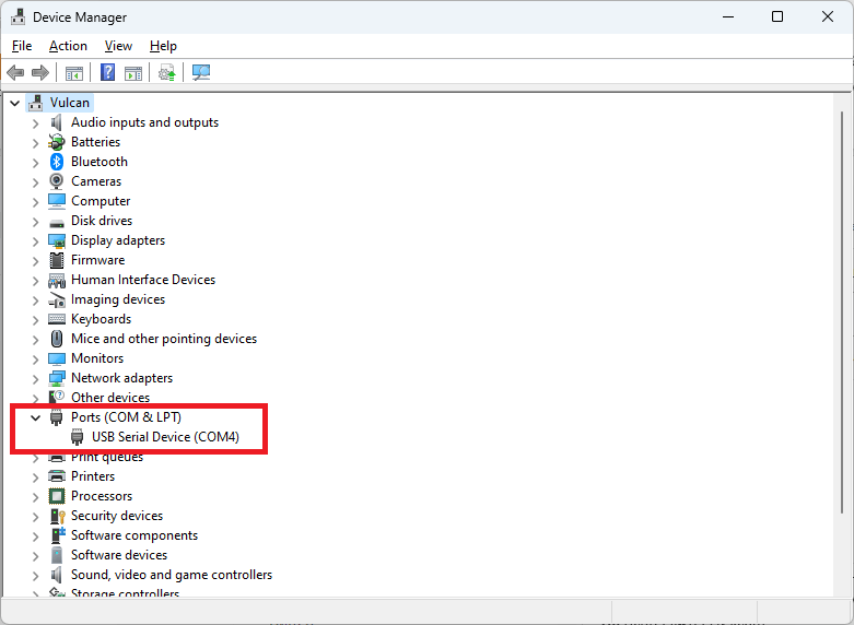
    • If this is not the first time, then a list of COM Ports are available. Open the Device Manager to see the available COM Ports and determine which one is the Pico board. You may unplug the Pico Board, wait for the Device Manager to refresh with one less COM Port, then plug the Pico board back in. Note, which new COM Port appears, that will be the one to select in the Arduino IDE.
Device Manager showing the Ports
Port, select the correct COM Port
  1. Open the example “Blink” sketch from the menu File > Examples > 01. Basics > Blink
  2. Click the “Upload” button in the Arduino IDE to load the sketch onto the Pico board
    NOTE: You may see several warnings about whitespace. These warnings may be ignored
Successfully uploaded sketch
  1. You should see the LED on the Pico board flashing once the sketch is uploaded

Hopefully, this gets you up and running. It is always a good idea to run the example blink program first when configuring a new board. It lets you know right away if things are working as expected. Once that works, then move onto your code.

Categories
Android Arduino Meshtastic Microcontroller Project Ideas Raspberry Pi Pico

Meshtastic Serial

I wanted to see about connecting a Raspberry Pi Pico to a LillyGo TTGO T-Beam v1.1 device. I noticed that Meshtastic supports serial communications, so I decided to give it a go to see how it worked.

There are several serial modes but the ones that seem the most useful are TXTMSG and PROTO. First attempt will be with the TXTMSG Mode as that seems straight forward. Once the TXTMSG Mode is working, I will look into how to use the PROTO Mode.

Wiring

We need to connect the grounds between the two devices, then connect the transmit (TX) from one to the receive (RX) of the other device. Below is a table showing the connections used in my setup.

T-BeamPico
RX pin 13TX pin 1 (GP0)
TX pin 14RX pin 2 (GP1)
GNDGND
T-Beam and Pico wiring
Wiring between T-Beam and Raspberry Pi Pico

Meshtastic Setup

Meshtastic firmware was installed using the Web Installer at https://flasher.meshtastic.org/. The T-Beam came with Meshtastic preinstalled. You may need to use another method to install the firmware if the Web Installer does not work.

Meshtastic Web Installer

T-Beam TEXTMSG Mode

Once Meshtastic has been installed on the T-Beam device and connected to the Android or Apple application, go to the Module Settings to setup the serial connection on the T-Beam device. The Module Settings is accessed by clicking on the kebab menu (aka three vertical dots menu) and selecting “Module Settings”.

kebab menu
Kebab Menu
Module Settings menu item

Once the Module settings are displayed, scroll down to the “Serial Config” section and set the following items.

  • Serial enabled: turn on
  • RX: Set it to the T-Beam pin number for receive, which is 13 in my setup.
  • TX: Set it to the T-Beam pin number for transmit, which is 14 in my setup.
  • Serial baud rate: May leave it at the default setting or set it to “BAUD_38400”. I think it is best to set it as the default baud rate may change in other versions. I believe I read that it did change in the past.
  • Serial mode: Set it to TEXTMSG
  • Once everything is set, click the “Send” button.
Serial Configuration

Pico Arduino Code

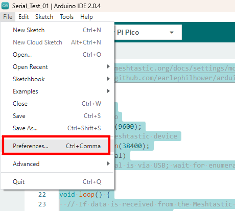
The Pico code is written in C++ using the Arduino IDE. It is necessary to configure use the Pico Board provided by Earle F. Philhower, III. First, add the URL, https://github.com/earlephilhower/arduino-pico/releases/download/global/package_rp2040_index.json, to the Additional Boards Manager URLs by going to File > Preferences in the menu.

Arduino Preferences Menu Item
Arduino IDE Preferences

Click the icon to the left of the “Additional boards manager URLs” entry. Add the URL to the a new line in the textbox and click the “OK” button.

Additional Boards Manager URLs

Open the boards manager by clicking on the boards manager icon, type “Pico” in the search textbox, and install the board, Raspberry Pi Pico/RP2040 by Earle F. Philhower, III.

Boards Manager
Boards Manager

Once the board is installed, you may select it from the boards dropdown selection in the IDE, when the Pico is connected to the PC.

Pico selected in the boards drop-down list
Raspberry Pi Pico selected in the boards drop-down list
/*
  Sample code to allow the Pico to act as a serial bridge between the PC and the Meshtastic device.

  Data sent to the Pico using the Arduino Serial Monitor, PuTTY, or other terminal software is sent
  to the Meshtastic device over the Pico UART0/Serial1 connection. Any data received from the Meshtastic
  device to the Pico is relayed to the PC over the Pico's serial over USB connection.

  REFERENCES:
    - https://meshtastic.org/docs/settings/moduleconfig/serial
    - https://github.com/earlephilhower/arduino-pico/discussions/210
*/

void setup() {
  // PC to Pico
  Serial.begin(9600);
  // Pico to Meshtastic device
  Serial1.begin(38400);
  while (!Serial)
    ;  // Serial is via USB; wait for enumeration
}

void loop() {
  // If data is received from the Meshtastic device, send it to the PC over the USB connection
  if (Serial1.available()) {
    String receiveMessage = Serial1.readString();
    Serial.print("Message received on Serial1 is:  ");
    Serial.println(receiveMessage);  // Send to serial monitor
  }

  // If data is received from the PC, send it to the Meshtastic Device
  while (Serial.available()) {
    int inByte = Serial.read();
    Serial1.write(inByte);
  }
}

Upload the code to the Raspberry Pi Pico. Once the code is loaded, open the serial monitor and type some text and hit enter. The message will be received on the other node(s).

Sending message from PC
Message received on other node

Sending a message from another node, will be received and shown in the serial terminal.

Sending message from another node
Receiving message on PC

Now the simple TEXTMSG is working, we can try to get the PROTO working. The PROTO mode is interesting as it may be possible to configure the Meshtastic device, and query it for additional information. I will look into the PROTO Mode in the near future.

Categories
Project Psion Raspberry Pi

Psion Sidecar Part II

I’m going to dive in a bit on the Psion Sidecar that I covered last week and add some details to explain the RS232 connections and the switches on the Sidecar.

Male DB9 Connector

Male DB9 Connector pinouts
PinFunctionI/O Direction
1Data Carrier Detect (DCD)Input
2Receive Data (RD)Input
3Transmit Data (TD or SD)Output
4Data Terminal Ready (DTR)Output
5Signal Ground (SG)
6Data Set Ready (DSR)Input
7Request to Send (RTS)Output
8Clear to Send (CTS)Input
9Ring Indicator (RI)Input
PC DB9 Pinout

Sidecar DB9 Pinout

The silkscreen and case markings were confusing me at first. It was a bit difficult to understand which switch position was for a straight Data Terminal Equipment (DTE) connection and which was for a Data Communications Equipment (DCE) connection. The silk screen on the PCB indicate that when both switches are toward the DB9 connector, that it is a straight DTE connection and when they are away from the DB9 connector, they are in the crossover/null modem DCE configuration. The case indicates that if they are to the left, as you look at the switch, then it is straight through and to the right is crossover configuration. These two were not in agreement.

Using an ohm meter to trace the connections through to the Raspberry Pi, it was apparent that the case was more correct but the opposite of what my thought was regarding the symbols. I thought that the straight arrow indicated that the DB9 was in a DTE pinout and the crossover symbol as the DCE connection. It is actually the opposite. I think that Kian may be indicating what device it is connecting to rather than what the DB9 pinout of the Psion Sidecar is when the switch is in a particular position.

Switch Positions

  • Left – DCE Pinout: Use when connecting to a PC or another device with DTE pinout.
  • Right – DTE Pinout: Use when connecting to the Psion, modem, or other device with a DCE pinout.
PinDB9
TX:RX
RTS:CTS
(Right DTE)
DB9
TX:RX
RTS:CTS
(Left DCE)
SP3232E
TX:RX
RTS:CTS
(Right DTE)
SP3232E
TX:RX
RTS:CTS
(Left DCE)
Raspberry Pi
TX:RX
RTS:CTS
(Right DTE)
Raspberry Pi
TX:RX
RTS:CTS
(Left DCE)
1Not ConnectedNot ConnectedNot ConnectedNot ConnectedNot ConnectedNot Connected
2RDTD13->1214<-1110 GPIO158 GPIO14
3TDRD14<-1113->128 GPIO1410 GPIO15
4Not ConnectedNot ConnectedNot ConnectedNot ConnectedNot ConnectedNot Connected
5SGSG151566
6Not ConnectedNot ConnectedNot ConnectedNot ConnectedNot ConnectedNot Connected
7RTSCTS7<-108->911 GPIO1736 GPIO16
8CTSRTS8->97<-1036 GPIO1611 GPIO17
9Not ConnectedNot ConnectedNot ConnectedNot ConnectedNot ConnectedNot Connected
DB9 to Raspberry Pi Pinouts
SP3232E IC Pinout showing buffers
SP3232E IC Pinout Showing Buffers

Properly shutting down the Psion Sidecar

To properly shutdown the Raspberry Pi in the Sidecar, open the Hermes or other terminal application. Connect to the Sidecar using telnet on port 23. Once connected, login and issue the command “sudo shutdown now“. Once the green light on the Raspberry Pi stops blinking, you may press the power button to turn the unit off.

Hermes used to properly shutdown the Raspberry Pi in the Sidecar.
Properly shutdown the Raspberry Pi in the Sidecar using Hermes Terminal application

Conclusion

I hope this is helpful in understanding how properly shutdown the Psion Sidecar and how to use the switches. Typically the switches will be in the right position to allow communication with a Psion 5mx device using the Psion BB9 cable.

Kian’s design is very nice as it allows the Psion Sidecar to be used for other things without the need of a null modem to connect it to another device. The only thing that you may need is a F-F gender changer and DB9 to DB25 adapters. This makes it a versatile device to connect other devices.

Categories
Project Psion Raspberry Pi

Getting Psion 5mx on the Internet

I found a project that Kian Ryan put together to get his Psion 5mx on the internet. It will not run YouTube or provide the content that we are used to today but it can provide a 1990’s internet experience.

Kian wrote up his build in a few of his blog posts. Below is a list of his blog posts. Please check them out for more details.

When I saw the video of Kian on Tom’s hardware, I immediately went to his blog to see how he put it together. I had been thinking of doing something similar and seeing what Kian had would save me a great deal of time. I do plan to make another version of his project using IrDA. I already have the parts that I believe I will need to make it happen. I want to get the RS232 version working first. I sourced and ordered the parts that I did not have on hand. A little over 2 weeks later, the last parts arrived so I could get started.

The first thing that I worked on was building the PiRS232 board. I had not paid attention to Kian’s instruction to use tall headers. I did not have tall headers on hand so I had to order some. A couple days later, the proper headers arrived so I could complete the build.

Parts List & Sources

  1. Raspberry Pi Zero W
  2. Pimoroni LiPo Amigo Pro
  3. Pimoroni LiPo SHIM for Raspberry Pi
  4. 2200mah LiPo Battery with JST connector
  5. Double ended JST connector
  6. 2×20 Long Male Header (19mm 16mm)
  7. M2.5 10mm+6mm Nylon stand-offs (F-M), screws and nuts
  8. M2.5 5mm screws
  9. M3 brass inserts
  10. M3 round head hex nut 8mm bolts
  11. Case
    • Quantity: 1
    • Source: Print the 4 STL files in the Case folder in Kian’s GitHub Repository. Optionally, you may printed on Printables
  12. Assembled PiRS232 board (See parts list below)
Parts laid out and numbered
Parts laid out and numbered. (NOTE: Header is not correct as it is a short header. There are brass inserts already in the case but extras are laid out. Only 2 brass inserts are needed. Double ended JST cable is shown as 2 JST pigtails. These will be made into one cable.)

Parts for the PiRS232 Board

  1. PCB for PiRS232 board
    • Quantity: 1
    • Source: Use the PiRS232.kicad_pcb in Kian’s GitHub Repository and have it made at PCBWay, OSHPark, or other PCB manufacturer. Another way is to go to the OSHPark project that I created and order it from there.
  2. SP3232E
  3. 0.1uF Capacitors
  4. Switch Slide DPDT
  5. DB9 Male Right Angle
PiRS232 Board Parts Numbered

3D Printing the Parts

I had printed the parts with ABS filament on an XYZprinting da Vinci 1.0 3D Printer. Below are the images from Simplify3D showing the orientation of the pieces.

PiRS232 Board Build

The first step was to solder the 0.1uF capacitors to the board.

Capacitors soldered to the board

Next was to install the SP3232E IC. Take note of pin 1 and orientate the IC correctly. Start by soldering 2 opposing corner pins. Make certain that the IC is mounted flush, then solder the remaining pins.

Solder the opposing corner pins of the IC
PiRS232 board with the IC installed

The switches were next. The same principle of soldering opposing corner pins, checking placement, then soldering remaining pins was done with the switches and then the DB9 connector.
Soldering the first switch
Both switches are in place
DB9 connector is installed

Putting the Stack Together

Once the correct headers arrived, I could get to work putting everything together and move on to the software.

Long and short headers compared
The regular and long headers. The long headers are need to put the stack together.

Soldering the long header to the Raspberry Pi Zero. The header that I have is 19mm but 16mm looks to be a better fit. After soldering the header, the excess needed to be trimmed with flush cutters. It is handy to use a breadboard to help keep the pins straight. It may be necessary to prop up the Raspberry Pi to keep everything straight. Again, start with opposite corner pins, check the alignment, adjust if necessary, then solder the remaining pins.

Place the LiPo Shim on the Raspberry Pi and solder in place. Make certain that it does not touch any components and remains parallel to the Raspberry Pi.

Install the 10mm+6mm standoffs with nuts.

I did not like how the pins from the switch were right on top of the power connection so I place a bit of electrical tape over the pins.

Secure the PiRS232 board to the standoffs and solder the header pins.

If your headers are long, then trim them flush with the board.

Secure the LiPo Amigo Pro to the 3D Printed Power Rest with two or three M2.5 5mm screws.

Checking the fit for the LiPo Amigo Pro, it looks like the screw for the DB9 connector is going to be in the way, so we will need to remove it. It also looks like the threaded bracket is in the way as well so that too needs to be removed.

The fit is better but it looks like we may still need to make an adjustment. We will see when it all goes into the case.

Everything is all wired up, now on to the software. It is tempting to install it in the case but we need to be certain that the software is configured and ready before stuffing it in the case as the card is not accessible once everything is installed.

Software Setup

Using the Raspberry Pi Imager, setup a headless installation. If you don’t have the Raspberry Pi Imager installed, head over to https://www.raspberrypi.com/software/ and download the Raspberry Pi imager. Once installed, launch it and click the “CHOOSE OS” button.

Click the “Raspberry Pi OS (other)” option

Click the “Raspberry Pi OS Lite (32-bit)” option.

Click the gear icon in the lower right corner.

Setup the following options.

  • Set a hostname
  • Enable SSH (Typically you will want to use password authentication.)
  • Set username and password to something that you will remember.
  • Configure wireless LAN with your network SSID and password. Make certain that your Wireless LAN country is poperly set as well.
  • Set local settings so your time zone and keyboard are correct.
  • Setup the persistent settings to your liking.

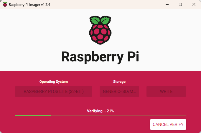
Click the “CHOOSE STORA…” button to select your microSD card, then click the “WRITE” button. The OS will be installed to your card. Once the verification completes and is successful, eject the card and put it in the Raspberry Pi. Start the Raspberry Pi by pressing the power button on the LiPo Amigo Pro.

SSH into the Raspberry Pi

If you don’t have PuTTY or other terminal software installed, now is a good time to head over to https://www.putty.org/ to download and install PuTTY. Once installed, open PuTTY and connect to your Raspberry Pi using the hostname that you setup when installing the OS to the card. If you cannot open a session, you may need to connect to your wireless router to determine the IP Address assigned to the Raspberry Pi and use that to connect.

Using one of the available text editors, edit /boot/config.txt. I’m using Nano, so I issued the following command. (Don’t forget sudo or you will be opening a read-only version.

sudo nano /boot/config.txt

Add the following lines at the end of /boot/config.txt, then reboot the Raspberry Pi.

# Disable Bluetooth - switch UART
dtoverlay=pi3-disable-bt

enable_uart=1

Install Hermes terminal emulator on your Psion device. On the PiRS232 board, the switches should be in the TX:TX/RX:RX and RTS:CTS/CTS:RTS positions.

NOTE TO SELF: It has been a long time since I needed to take a screenshot on a Psion device. On the 5mx, press CTRL+FN+SHIFT+S. On Windows, use an application such as XnView to open the screenshot and convert to another format.

Once the Raspberry Pi reboots and Hermes is installed on the Psion, open Hermes. On the menu, select Connection> Connection… (or Ctrl+K). Select the following options, then click the “OK” button.

  • Comms: Serial port 0
  • Baud rate: 115200
  • Settings: 8 data; 1 stop; No parity
  • Handshaking: Hardware (RTS/CTS)

If you get a dialog stating “Opening serial port Access denied”, you will need to disable the remote link.

On the System screen, open the menu and select Tools > Remote link… (or Ctrl+L).

Change the Remote Link setting to “Off”.

When connected to the Raspberry Pi, it may be necessary to press the Enter key once or twice to receive the login prompt from the Raspberry Pi.

It is now possible to work directly from the Psion or using PuTTY.

Setting up Flow Control

These commands may be entered from the Psion or PuTTY. I’m using PuTTY because it is easier to copy and paste. Issue the following commands.

sudo apt-get update

sudo apt install build-essential git
git clone https://github.com/mholling/rpirtscts 
cd rpirtscts
make
sudo ./rpirtscts on

wget https://github.com/HiassofT/AtariSIO/blob/master/contrib/rpi/uart-ctsrts.dtbo?raw=true -O uart-ctsrts.dtbo
sudo mv uart-ctsrts.dtbo /boot/overlays/

sudo nano /boot/config.txt

Add the following at the end of /boot/config.txt, then save the file and exit the Nano editor. The first, second, and the last lines should already exist from the last step, when we edited the /boot/config.txt file. We are adding the third line here.

# Disable Bluetooth - switch UART, enable CTS/RTS
dtoverlay=pi3-disable-bt
dtoverlay=uart-ctsrts
enable_uart=1

Once the file has been saved and we are back at the command line, edit ~/.bashrc file by issuing the following command.
NOTE: Kian edits ~/.bash_rc but that file did not exist and creating it and adding the line did nothing. I needed to edit ~/.bashrc instead. Editing ~/.bashrc enabled flowcontrol for my setup.

nano ~/.bashrc

Add the following line at the end of the file.

stty -F /dev/ttyAMA0 crtscts

When using PuTTY or other SSH application, you may notice that there is an error when you login that states, “stty: /dev/ttyAMA0: Permission denied”. This is not an issue and does not show on the Psion 5mx serial connection. It may be possible to edit ~/.bashrc to only execute the command that we added if there are connected over a serial connection. That will take some further investigation but is a low priority. If you know how to detect the connection type and how to change the ~/.bashrc file, please leave a comment.

Optional – Install CMatrix

CMatrix is not necessary to install but it is a good test for the serial connection and it just looks cool. From either PuTTY or the Psion, issue the following commands to install and run CMatrix.

sudo apt-get install cmatrix

cmatrix

CMatrix runs slow on the Psion 5mx with a serial connection but it works. To exit, press Ctrl+C.

Setting Up Point-to-Point Protocol (PPP)

If you have not already, please read Kian’s PPP setup and understand the security concerns and understand that the serial terminal will no longer be available after this step.

Run the following commands from PuTTY.

sudo apt install ppp

sudo nano /etc/rc.local

Add the following two lines to /etc/rc.local before “exit 0”, save the file, and exit the editor.

stty -F /dev/ttyAMA0 raw
sudo pppd /dev/ttyAMA0 115200 10.0.0.1:10.0.0.2 proxyarp local noauth nodetach dump crtscts passive persist maxfail 0 holdoff 1 &

Start raspi-config by issuing the following command.

sudo raspi-config

When Raspberry Pi Software Configuration Tool launches, go to Interface Options > Serial Port. Select “No” for shell and “Yes” for enabled.

Verify that the confirmation message states that the serial login shell is disabled and that the serial interface is enabled.

If the configuration is correct, select finish to exit and reboot the Raspberry Pi.

Setting Up the Psion

Jump over to Kian’s instructions.

I ran into an issue when attempting to connect to the internet. Hermes would not connect.

The issue turned out to be quite obvious once it dawned on me that telnet server does not exist on the Raspberry Pi. There is a good reason that it is not installed. Telnet is a security concern as it is unencrypted. Keep this in mind if you install telnet on your Raspberry Pi. To install telnet, run the following command.

sudo apt-get install telnetd

Once telnet server was installed, things worked as Kian has in his blog post.

Web Browsing

Opera is the best web browser for Psion devices, but it has only a 30-day demo. You need a license to use it past 30 days. It can be downloaded from https://get.geo.opera.com/pub/opera/. It looks like the latest version (19 April 2002) is at https://get.geo.opera.com/pub/opera/symbian/514/en/er5/.

Well, I hit another snag. It appears that I cannot connect to the internet through the Raspberry Pi. DNS was not resolving domain names, so I attempted to browse by IP Address but that did not work either.

To fix this issue, we need to do a bit more configuring on the Raspberry Pi. I found a couple of posts that helped me figure out how to fix the issue.
SOURCE: https://www.instructables.com/Connect-the-Raspberry-Pi-to-network-using-UART/ and https://www.ducea.com/2006/08/01/how-to-enable-ip-forwarding-in-linux/

The following two commands are a temporary way to get it all working.

sudo sysctl -w net.ipv4.ip_forward=1

sudo iptables -t nat -A POSTROUTING -o wlan0 -j MASQUERADE

A more permanent solution is to edit /etc/sysctrl.conf and /etc/rc.local. First edit /etc/sysctrl.conf by using the following command.

sudo nano /etc/sysctl.conf

Find the commented line “#net.ipv4.ip_forward=1” and uncomment it, save the file, and exit the editor.

# Uncomment the next line to enable packet forwarding for IPv4
net.ipv4.ip_forward=1

Next edit /etc/sysctrl.conf by using the following command.

sudo nano /etc/rc.local

Add the following line before “exit 0”, then save the file and close the editor.

iptables -t nat -A POSTROUTING -o wlan0 -j MASQUERADE

Reboot the Raspberry Pi. Once the Raspberry Pi reboots, attempt to browse the internet on the Psion.

Closing Up the Case

Now that the software is in working order, we can put everything in the case and close it up. First start by carefully placing the stack in the case. It is a bit of a challenge to get the standoff into case without breaking the case but it will go, you just need to be careful.

The standoffs don’t protrude through the bottom, so no worries that it will scratch the table. 😉

The DB9 screw did not hit the Pimoroni LiPo Amigo Pro, so I was able to put it back on, then I installed the Pimoroni LiPo Amigo Pro on its self by attaching it with one M2.5 5mm screw.

Installed the battery and taped down the wires so they were not in the way of the switch.

Now close it up by attaching the lid with the M3 screws. I used a bit of tape to keep the button in place while I put it all together.

Categories
Desktop Application Development Project Raspberry Pi Software Development

Soft Latching Power Switch Revisited

This week, I have some updates revolving around the Soft Latching Power Switch, that I last wrote about eight years ago. I finally returned to the project and now have it working as I intended. I also have made some changes to the Dual Volt Amp Meter‘s Desktop software. I believe I may now have a stable usable version. Lastly, I’ve gotten started with Flux.ai and plan on using it to replace my old version of Eagle.

Soft Latching Power Switch

Soft Latching Switch on the bench
Soft Latching Switch on the bench connected to a Raspberry Pi Zero

I resolved a few items that I encountered previously when I attempted to use the Soft Latching Power Switch designed by Mosaic Industries to control an Adafruit 1000C. I was able to reliably control the PowerBoost 1000C using the Soft Latching circuit, one I removed R13 from the PowerBoost and placed a 200K ohm resistor between the enable and ground. R13 pulls up the enable pin to Vs so that the PowerBoost is always on, unless the enable pin is connected to ground. In my case, I wanted the opposite behavior. I wanted the PowerBoost to always be off unless the enable pin is connected to Vs.

The Soft Latching Power Switch designed by Mosaic Industries is intended to switch the 5V going into the Raspberry Pi but I wanted to use it differently by having it control turn off, or disable, the PowerBoost 1000C boost circuit. Below is a diagram showing the circuit used in this design.

Complete Circuit Diagram
Complete Circuit Diagram with the Soft Latching Circuit, Powerboost 1000C, and Raspberry Pi

The Soft Latching Power Switch is connected so that the input voltage is the Vs output of the Adafruit 1000C. The Vs output is USB voltage if USB Power is applied. If USB Power is not applied, Vs is the battery voltage. The output of the Soft Latching Power Switch output is connected to the enable pin of the Adafruit 1000C. The final connection of the Soft Latching Power Switch is the control pin, which is connected to GPIO22 (pin 15) of the Raspberry Pi.

The Adfruit PowerBoost 1000C is modified by removing the 200K ohm pull-up resistor, R13. An external 200K ohm resistor is connected between the enable pin and ground. A capacitor, around 0.01uF is placed in parallel with the resistor to prevent the PowerBoost from turning on the first time power is applied from either USB or battery. The value of the capacitor used is not critical. The first capacitor I grabbed was 0.01uF and it worked. The purpose of the capacitor is to make it look like a short from the enable pin to ground when power is first applied. If you find that it still starts from the on state rather than off state, you may need to use a higher value capacitor to provide more time for the capacitor to charge up and appear as a short to ground.

Once the circuit is put together and connected, you will need to load some scripts on the Raspberry Pi to allow the switch to shutdown the Raspberry Pi when the switch is pressed and for the Raspberry Pi to turn off the power when it shuts down. The scripts are available in the Pi-Power-Button project on GitHub.

This setup provides the following functionality:

  • Button press to turn on
  • Button press to signal to the device to shutdown
  • Long button press to force power off
  • Turn off power when the Raspberry Pi shuts down

Next Steps

  • Clean up the code now that it is working as expected
  • Possibly have one script file to handle shutdown and listening for button press
  • Design another circuit to allow similar functionality from a keyboard similar to the functionality on the HP 95lx and Psion 5 PDAs

Dual Volt Amp Meter

Made some changes on the desktop application for the Dual Volt Amp Meter project that I wrote about a few weeks ago.

I was having some issues with the software after it was running for a few hours. I would get random errors related to an index being out of bounds and could not figure out how that was possible when I am in a for loop that has the lower bound being zero and the upper bound being one less than the count of items in the list. I neglected to connect the dots that I was manipulating the list in another thread to limit the number of items in the list. The error would crop up if the timing was just right that the check on the array bounds occurred on the main thread, then the code then removed the item on the other thread. The next line in my main thread then referenced the item that was just removed, then the application would crash.

I believe I have now resolved all of those issues, so the code should be stable now. It has been running for a couple of hours so far without any issues.

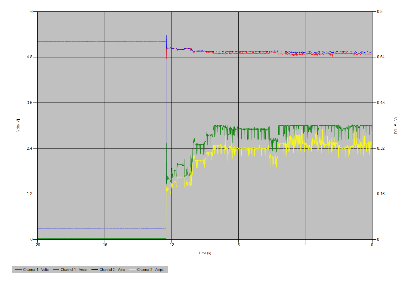
Below is a capture from the application showing the button on the Soft Latching Power Switch being pressed and turning on the PowerBoost 1000C and in turn, the Raspberry Pi.

Graph from from the Dual Voltage Amp Meter
Graph from from the Dual Voltage Amp Meter showing the Soft Latching Power Switch being turned on.

Flux.ai

I discovered Flux.ai by watching a hackster.io video, where Alex Glow interviewed the Flux.ai team. I have since started working with Flux.ai and intend to create the Soft Latching Power Switch publicly in Flux.ai so others may use in their designs.

I really like what the Flux.ai has put together but it feels like there is much work to do to make it a product that may be used by the community. I plan to work more with Flux.ai and provide feedback to the team on design changes that may help users come up to speed quickly.

The only Schematic and PCB Layout tool that I have used successfully was Eagle. Once Eagle was acquired by Autodesk and moved to online subscription based licensing, I stopped updating Eagle. I’m still using Eagle 7.7.0 and would like to move on to something else. I have looked at KiCad and have it installed but have not made the commitment to start using it. Part of the reason is I have several components that I built in Eagle. I would need to start over in KiCad.

Another reason I have not moved to KiCad but am willing to move to Flux.ai, has to do with the parts libraries when sharing a project. I have received or pulled KiCad designs and have had to reach out to the authors to get some missing libraries. (The same is an issue with sharing Eagle designs.) Flux.ai solves this problem as libraries are online and may be shared with the community.

In addition to public parts, Flux.ai has the ability to create pull completed circuits with PCB layouts in other designs. This is great as one may design a power supply or other circuit and pull it in and reuse it in multiple projects. I have attempted something similar in Eagle but there are always issues with it and it seems you are always reinventing the wheel. Flux.ai eliminates redundant work and speeds up the design process.

Another advantage of Flux.ai is they have brought change management into the tool. You may see all the revisions made to a part or circuit, stay on an older version, or update to the latest change. This allows someone to update their public design to fix an issue and someone else who has used the design, may pull the latest fix into their design. It also allows someone to fork someone else’s design, improve upon it, then submit a pull request so the original designer can pull the change and everyone may benefit.

As you can tell, I’m very hopeful that Flux.ai will succeed and the Open Source community will embrace what Flux.ai is attempting to do with their hardware design platform. Give it a try. I hope to see the community help Flux.ai grow.

You may see what I’m up to on the platform by going to https://www.flux.ai/richteel. So far, I’ve put together one part for the IRF7319. I did so by forking another user’s part for the IRF7317.

Categories
Project Raspberry Pi Pico

Dual Volt Amp Meter

Photo of the finished Dual Channel Voltage and Current Monitor reading two USB voltages and loads

Overview

This writeup is from the GitHub pages for the VoltsAmpsLogger project and from the hackster.io project page. The code is in the VoltsAmpsLogger GitHub Code Repository

The Dual Channel Voltage and Current Monitor project was created as I needed a way to look at the voltage and current going into an Adafruit Powerboost 1000c module and through the soft switch circuit that I built from Mosaic Industries Raspberry Pi ON/OFF Power Controller. I wanted to be able to monitor the voltage and current coming out of the controller and going into the Raspberry Pi.

The project is based on the Adafruit INA219 High Side DC Current Sensor Breakout and a Raspberry Pi Pico. The Raspberry Pi Pico is a bit overkill for this project, but I have a few on hand so that is what I choose to use.

Hardware Build

Parts List

Next Steps/Going Further

The data transfer rate is extremely slow. It is good enough for what is being done here but it would be nice to capture more data points over the same period. Right now, the rate is about one set of measurements per minute. (It takes about 1.2 seconds to send one set of measurements.) One way to speed this up would be to move away from JSON and sending tab delimited data. I may create another version of the Raspberry Pi Pico and Windows software to send delimited data and see if there is an improvement. I would expect to get 4 to 5 times as many measurements in the same amount of time. It still is not very fast, but it would be an improvement.

References

External Project Pages