Categories
Meshtastic Raspberry Pi Software Development

Meshtastic with Raspberry Pi (Serial) – Part IV

In this part of the Meshtastic with Raspberry Pi (Serial) series, we will be writing some code to test the connection, then adding to our code to send sample data. When sending data, we will format the message to allow us to reject data if it is not formatted correctly and do some simple error detection.

A good resource, which will be used to write this code may be found on the “Raspberry Pi UART Communication using Python and C” page on the ElectronicWings site.

Preparation

You need to start off by editing the cmdline.txt file to remove the console=serial0,115400 argument and value. If you don’t do this, you will see errors similar to ‘device reports readiness to read but returned no data’. More information and background is available at https://raspberrypi.stackexchange.com/questions/111817/serial-serialutil-serialexception-device-reports-readiness-to-read-but-returned

On the Raspberry Pi, open a terminal window or use PuTTY to run the following command.
sudo nano /boot/cmdline.txt

Initial cmdline.txt opened in nano editor

Comment out or delete the “console=serial0,115400” in the line.

Modified cmdline.txt opened in nano editor

Once the cmdline.txt has been modified, restart the Raspberry Pi.

NOTES: If the console=serial0,115400 is missing, you skipped enabling the serial port from the raspi-config tool. Look back at the earlier posts in this series for instructions on how to enable the serial port. It is also possible that the baud rate in the command is something other than 115400 so you may see a different baud rate, which is fine, but you will need to remove that argument from the file.

Test Program

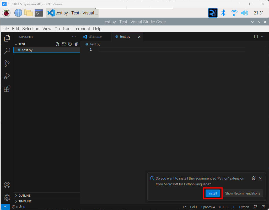
Now that the serial port is properly configured, we can write a simple program and test the T-Beam connection to the Raspberry Pi. On both Raspberry Pi boards, create a uart.py file with the following code.

'''
UART communication on Raspberry Pi using Python
http://www.electronicwings.com
'''
import serial
from time import sleep

ser = serial.Serial ("/dev/ttyS0", 38400)    #Open port with baud rate
while True:
    raw_data = ser.read()              #read serial port
    sleep(0.03)
    if raw_data:
        data_len = ser.inWaiting()
        raw_data += ser.read(data_len)              #read serial port
        received_data = str(raw_data, "utf-8")
        print (received_data)                   #print received data

The code will listen for data on the serial port and will print the received data in the terminal window. Run the code on both Raspberry Pi boards by typing the following command.
sudo python uart.py

On the Android device, open the Meshtastic application and type a message and press the send button.

Meshtastic App with Phoebe sending the message "Hello Rachel"

The message will be displayed in the terminal window of the receiving Raspberry Pi device.

Message "Hello Rachel" received in the terminal window

Sample code sending and receiving data

Before using the following example, it is suggested to change the serial configuration to “Simple” and creating an additional channel named “serial”. Screenshots were taken of the Meshtastic application and placed into a Google Album. Refer to the album if you have any questions regarding what configuration values were used for this example.

The sample code will send CPU Temperature data twice per minute. Below are a few notes/requirements.

  • The data will be sent as JSON.
  • The data will be contained in a Python Dictionary with string values for the keys.
    Sample keys:
    • t: Time in UTC ISO 8601 format without milliseconds
    • nam: The host name of the Raspberry Pi
    • cput: CPU Temperature in degrees Celsius
  • Float values will be sent as formatted strings with the precession required for the application. As an example, temperature will be sent with two decimal values.
  • The total length of the message shall not exceed 200 bytes. In practice, it should be kept well below 200 bytes. This requires that the keys for the key value pairs to be kept short.

Example Code:

The following example code was written to meet the above requirements.

'''
- References -
--------------
ISO 8601
    https://pynative.com/python-iso-8601-datetime/
UART communication on Raspberry Pi using Pyhton
    http://www.electronicwings.com
'''

import serial
import time
from datetime import datetime, timezone
import re
import socket
import json

def get_temp():
    with open('/sys/class/thermal/thermal_zone0/temp', 'r') as infile:
        return float(infile.read()) * 1e-3

# Open port with baud rate
ser = serial.Serial("/dev/ttyS0", 38400)
# Set the start time in the past so that the first data point will be sent at the startF
start = time.time() - 600
# Create a variable for the received data.
received_data = ""
# Flag for knowning if the error for T-Beam being disconnected has been displayed
no_serial = False

try:
    while True:
        data_len = 0
        data_len = ser.in_waiting
        utc_dt = datetime.now(timezone.utc).replace(microsecond=0)

        if data_len > 0:
            raw_data = ser.read(data_len)  # read serial port
            try:
                received_data += str(raw_data, "utf-8")
                x = re.search("\{.*\}", received_data)
                if x:
                    # PuTTY changes tab characters to spaces so we will use the pipe symbol
                    # print(F"{utc_dt.isoformat()}\tRECV\t{x[0]}")
                    print(F"{utc_dt.isoformat()}|RECV|{x[0]}")
                    received_data = ""
                if no_serial:
                    no_serial = False
            except UnicodeDecodeError:
                received_data = ""
                if not no_serial:
                    print("ERROR: The serial connection may be down")
                    no_serial = True

        if time.time() - start > 30:
            start = time.time()
            temp = get_temp()
            dat = {
                "t": utc_dt.isoformat(),
                "nam": socket.gethostname(),
                "cput": F"{temp:0.2f}",
            }
            if len(json.dumps(dat)) < 200:
                ser.write(bytes(json.dumps(dat), "utf-8"))
                # PuTTY changes tab characters to spaces so we will use the pipe symbol
                # print(F"{utc_dt.isoformat()}\tSENT\t{json.dumps(dat)}")
                print(F"{utc_dt.isoformat()}|SENT|{json.dumps(dat)}")
            else:
                print(
                    F"ERROR: Data length is greater than 200 bytes (length={len(json.dumps(dat))})")

except KeyboardInterrupt:
    print("\r\nExiting")
# finally:
#   GPIO.cleanup()

Below is the output from both Raspberry Pi boards running the code with the same T-Beam Meshtastic settings.

Two PuTTY windows side-by-side with each connected to separate Raspberry Pi boards

An Excel workbook was put together to check the delay from transmit and receive as well as identifying packets being received out of order. Previous runs with slightly different code did contain out of order packets so it should not be assumed that packets will be received in order. Below is the Check.xlsx file that you may download.

Below are some statistics from the Check.xlsx Excel Workbook with data produced from 27 minutes runtime of the sample code.

  • pi-sensor01
    • Receive Delay (hh:mm:ss)
      • Min: 00:00:07
      • Max: 00:04:12
      • Average: 00:01:28
      • Median: 00:00:57
    • Data Received out of order: 0
    • Data Points
      • Total: 104
      • Sent: 56
      • Received: 48
    • Sent Packets Received by pi-sensor01:
      • Received: 55
      • Not Received: 1
      • Percent of Packets Received: 98.21%
  • pi-sensor02
    • Receive Delay (hh:mm:ss)
      • Min: 00:00:07
      • Max: 00:01:35
      • Average: 00:00:23
      • Median: 00:00:15
    • Data Received out of order: 1
    • Data Points
      • Total: 111
      • Sent: 56
      • Received: 55
    • Sent Packets Received by pi-sensor01:
      • Received: 48
      • Not Received: 8
      • Percent of Packets Received: 85.71%

Going Further

This is the end of this series at least for now. It was put together to provide some information with one way to send data between two Raspberry Pi devices using serial communications. There are other ways to send data using the serial port. One of the more interesting ways may be using the PROTO mode for the Meshtastic serial port. It looks like using the PROTO mode may allow for the code to setup and configure the Meshtastic device. If that is the case, it may provide much more control and standardization across connections. (Meshtastic Serial Port Configuration)

Another area to look into is how to improve the successful delivery of messages in a timely manor. It may be sending messages every 30 seconds was too fast and flooded the available channels. It may also be possible that the store and forward setting was misunderstood and caused message flooding on the channel. The devices may have been too close together to provide reliable communications. All of these things and others could be looked into to see if it is possible to create more reliable communications.

Categories
Meshtastic Raspberry Pi Software Development

Meshtastic with Raspberry Pi (Serial) – Part III

In this part of the Meshtastic with Raspberry Pi (Serial) series, we will be installing Meshtastic to the LilyGo T-Beam devices. We will then create a Meshtastic Channel on one LilyGo T-Beam and replicate the channel to the other LilyGo T-Beam. We will then wire the Raspberry Pi and LilyGo T-Beam devices.

Install Meshtastic Firmware on the LilyGo T-Beam devices

Visit the Meshtastic Web Installer at https://flasher.meshtastic.org/. Select the following options:

  • Device: Tbeam
  • Firmware Version: Select the latest version.
    NOTE: May want to install latest beta version if you want the most stable version available.
  • Update or reinstall: Either option is fine. A reinstall may wipe out any settings that you have configured on the device but may be the best option for the first installation.
Meshtastic Web Installer

Click the “CONNECT” button

Select the serial port that the T-Beam is connected to. If you are uncertain, you may open the Windows Device Manager and look at Ports (COM & LPT), then look for “USB-Enhanced-SERIAL CH9102” or similar device to find the serial port.

Meshtastic Web Installer - Select COM Port

Click “INSTALL TBEAM”

Meshtastic Web Installer - Install TBeam

Click “INSTALL”

Meshtastic Web Installer - Install

You will see the progress as it installs the firmware.

Meshtastic Web Installer - Installing
Meshtastic Web Installer - Installing 38%

When the installation is complete, click “NEXT”

Meshtastic Web Installer - Installation Complete

You may then click the X in the device dashboard to close the dashboard.

Meshtastic Web Installer - Close Device Dashboard

Repeat the steps for the other T-Beam, then close the browser.

Configure T-Beam and Create Channel

Using a mobile phone, tablet, or PC, open the Meshtastic App or Web Client. The following examples will show the Web Client and Android App.

Web Browser on a PC

It is best to use the Android application to configure the T-Beam device. The instructions provided here for the Web Browser are incomplete as I could not determine how to set some of the options that I know are available in the Android Application. These instructions are provided to demonstrate how to access the configuration from the web browser.

With the LilyGo T-Beam connected to the PC, open a browser and navigate to https://client.meshtastic.org/. Click the “New Connection” button.

Web configuration main page

The “Connect New Device” dialog is shown. Click the “New device” button.

Web configuration - Select device

Select the T-Beam device from the list of devices and click the “Connect” button.

Web configuration - Connect New Device Screen with new device listed

Click the device from the device list.

Web configuration - Connect New Device Screen - Close button

The selected device will turn gray to show that it is selected. Click the X in the top right corner of the “Connect New Device” dialog to close the dialog box.

Web configuration - LoRa Configuration

Android App

If the Meshtastic application is not already installed, go to the Play Store and search for an install the Meshtastic App.

Play Store - Meshtastic App

Open the Meshtastic Application and click the gear icon in the top toolbar on the right, then click the “+” in the lower right corner to add a new Meshtastic device.

Meshtastic Devices Screen

On the T-Beam device, look for the device name on the LCD screen.

Meshtastic T-Beam LCD Screen

In the Meshtastic App, select the device name that matches the name on the T-Beam LCD Screen, in the list of available devices.

Meshtastic App - Device Link Selection List

The T-Beam device will display a Bluetooth pin on the LCD Screen.

Meshtastic T-Beam LCD Screen with Bluetooth Pin

Enter the Pin in the Bluetooth pairing request screen and click “OK”.

Meshtastic App - Enter Bluetooth Pin

Next, we need to set the region by clicking on the region dropdown.
NOTE: Make certain that the correct device is selected.

Open region dropdown list

Select your region from the list. My region is “US”, so that is what I selected.

Select region

The selected region will be displayed in the application and the T-Beam device will reboot.

Meshtastic App - Region Set

Once the device reboots, you may enter a name if you like. Do not move off this screen right away or the name may not stick. You may find that you need to reenter the name a few times before it is saved.

Meshtastic App - Change Name

Click on the hamburger menu in the upper right corner and select “Radio configuration”.

Meshtastic App - Hamburger Menu

Click on “Serial” from the “Radio configuration” menu.

Meshtastic App - Radio configuration menu

Enter the settings for the Serial Port, then click the “Send” button.

  • Serial enabled: Turn on
  • RX: Pin 13
  • TX: Pin 14
  • Serial baud rate: Selected 38400 baud but may select different rate. Make certain this matches when writing code on the Raspberry Pi.
  • Serial mode: TEXTMSG
Meshtastic App - Serial Settings

If you want a private channel, setup the channel on one device, then scan the QR Code on the other devices in the Mesh. I will not go over setting up a channel. For more information on setting up a channel, go to Meshtastic’s Channel Configuration page.

Wire Everything Up

The connection between the Raspberry Pi and the T-Beam device only requires three wires. A wire for the ground and two for the serial connection. The serial connection will cross the transmit (TX) and receive (RX) wires so that the TX from the Raspberry Pi is connected to the T-Beam RX and the Raspberry Pi RX will connect to the T-Beam TX. Below is a diagram showing these connections.

Wiring diagram for Raspberry Pi board connected to LilyGo T-Beam device
Categories
Meshtastic Raspberry Pi Software Development

Meshtastic with Raspberry Pi (Serial) – Part II

In Part I, we installed the Raspberry Pi OS and connected to the Raspberry Pi using PuTTY and VNC from another PC. In Part II, we will install Visual Code on the Raspberry Pi to allow us to code directly on the Raspberry Pi using a modern IDE.

It is not required to install Visual Studio Code. There are several options for writing programs and running them on the Raspberry Pi. It is possible to simply use the Text Editor on the desktop, Nano or VI from the terminal, or use an editor on the PC and transfer files using WinSCP.

Installing Visual Studio Code

The first thing to note is that the Chromium web browser is not going to work well on older Raspberry Pi boards. I am using a Raspberry Pi 3, so it is necessary to open a terminal and run the following command to launch the Dillo web browser:
dillo

Once the browser is open, navigate to https://code.visualstudio.com/download.

Dillo web browser showing the Visual Studio Code download page

Clicking on the .deb Arm32 link does nothing as the link is using JavaScript to download the correct file. We will need to get the installation package from our PC and move it to the Raspberry Pi.

On the PC, navigate to https://code.visualstudio.com/download and click the .deb Arm32 link to download the installation package. Save it to a known location and remember where you saved it.

Open WinSCP and connect to the Raspberry Pi.

WinSCP Login window

If it is the first time connecting to the Raspberry Pi, you will see a Warning dialog. Click “Yes” to continue.

WinSCP Warning dialog for unknown host

Once connected, in the right pane of the WinSCP application, navigate to the desktop folder on the Raspberry Pi and in the left pane, navigate to the location of Visual Studio Code installation package on your PC. Once the locations have been selected, you may click and drag the installation package from the PC to the Raspberry Pi.

WinSCP window transferring the Visual Studio Code installation package

Once the package has been transferred, switch to VNC Viewer and you will see the file on your desktop.

Raspberry Pi desktop with Visual Studio Code installation package

Right-click on the installation package and select “Package Install” from the context menu.

Package Install on right-click context menu

Once the installation completes, you may launch Visual Studio Code from the menu by navigating to Programming > Visual Studio Code.

NOTE: You may delete the Visual Studio Code installer from the desktop if you wish.

Raspberry Pi OS Menu showing Visual Studio Code
Visual Studio first launch

I like to use the Explorer, the top icon on the left toolbar, to open a folder. From there, I may create files and folders for the project. In the screenshot below, I have created a folder named “Test” in my home folder and added a file named “test.py”. Once I created the file, Visual Studio Code recognized that I created a Python file and prompted me to install the Python language extension.

Visual Studio Code with prompt to install Python language extension
Categories
Meshtastic Microcontroller Raspberry Pi Software Development

Meshtastic with Raspberry Pi (Serial) – Part I

In this post, I will step through getting Linux installed on a Raspberry Pi with an overview of different installations, and detailed setup on a headless installation. I will then move into connecting the Raspberry Pi to a LilyGo T-Beam device with Meshtastic Firmware, with the connection to the Raspberry Pi using a Serial Connection. Connecting one or more sensors to the Raspberry Pi, and finally sending that data to another Raspberry Pi connected to a LilyGo T-Beam.

Before Installing Linux on Raspberry Pi

There are several options for installing Linux on the Raspberry Pi. The first question to answer is, which distribution to use? There are several different distributions available for the Raspberry Pi boards. A comprehensive list of distributions available may be found at https://elinux.org/RPi_Distributions. The distribution that I will be using is Raspberry Pi OS by Raspberry Pi.

The next question to answer is do we want a desktop or do we wish to run in headless mode? Installing a desktop is helpful if we wish to use the Raspberry Pi as a regular computer with a nice user interface. Installing a desktop does require more resources but makes the Raspberry Pi more useful if we wish to connect it to a display and keyboard or use VNC from another machine.

A headless mode installation is best if we only need to work from the terminal (command line) and/or we want more resources for running applications to monitor sensors or server up web pages or application program interfaces (API).

The last question to ask is what peripherals and options do we need to have configured? We know we will want the serial interface enabled, since that will be used to communicate to the LilyGo T-Beam devices. Depending on the sensors that we wish to use, we may want to enable the I2C interface.

Another option we will want is to be able to control the Raspberry Pi from another machine as we do not want to connect a monitor, keyboard, and mouse. We will need to enable SSH and VNC to allow control from another machine.

Below is a list of our installation options that we will configure.

  • Distribution: Raspberry Pi OS
  • Mode: Desktop
  • Enable SSH
  • Enable VNC
  • Enable Serial
  • Enable I2C

We have a couple of ways to enable the above configuration but we will configure all of these options from the Raspberry Pi Imager as it makes this relatively easy and quick. The toughest part is determining what the IP Address is of the Raspberry Pi when it boots up.

Required software on the Windows, Linux, or Apple PC

There is some software that we need to have on the PC in order to install the Raspberry Pi OS and control it from the PC.
If the listed software does not support your operating system, look for a similar application for your operating system.

Prepare SD Card for Raspberry Pi

  1. Insert an SD Card in your PC and note the drive letter. Make certain that the SD Card does not have anything that you wish to keep as the card will be wiped, so your information will be gone.
Windows Explorer showing drives with SD Card highlighted
  1. Open the Raspberry Pi OS Imager and click the “Choose OS” button
    In Windows, you will be prompted by the User Account Control (UAC) to continue. Select “Yes”
Raspberry Pi OS Imager window with Choose OS highlighted
  1. Select “Raspberry Pi OS (32-bit)
Raspberry Pi OS Imager - Operating System Listing
  1. Click the button in the lower right corner, with the gear icon for the advanced settings
Raspberry Pi OS Imager with Advanced Options button highlighted
  1. Set the hostname (optional but recommended)
  2. Make certain that “Enable SSH” is checked and “Use password authentication” is selected
  3. Change the password and optionally change the username
  4. Enter the settings for your WiFi connection if not using ethernet
  5. Optionally set time zone and keyboard layout
  6. Once the options have been set, click the “Save” button
Raspberry Pi OS Imager Advanced Options
  1. Click the “Choose Storage” button
Raspberry Pi OS Imager window with Choose Storage highlighted
  1. Select the SD Card identified earlier. Make certain that this is the SD Card as all data will be wiped from the selected drive and will not be able to be recovered.
Raspberry Pi OS Imager showing the list of storage devices that may be used
  1. Click the “Write” button to write the OS image to the SD Card
Raspberry Pi OS Imager window with the "Write" button highlighted
  1. If you are absolutely certain that the correct SD Card has been selected and there is no data on the card that you wish to keep, click the “Yes” button.
Raspberry Pi OS Imager window with the "Yes" button highlighted on confirmation dialog
  1. Once the image has been written to the SD Card, you may click the “Continue” button, close the Raspberry Pi OS Imager, and remove the SD Card from the PC, and insert it into the Raspberry Pi.
Raspberry Pi OS Imager  showing the "Write Successful" dialog
  1. Once the SD Card is inserted into the Raspberry Pi, connect power to the Raspberry Pi
  2. After a couple of minutes, open PuTTY on your PC and attempt to connect to the Raspberry Pi using the name provided in the advanced options of the Raspberry Pi OS Imager. In the example, “pi-sensor01.local” was used. In PuTTY, attempt to connect using the hostname provided in the image configuration.
    NOTE: If configuring another Raspberry Pi, do not use the same hostname.
PuTTY Configuration window showing the options for connecing to SSH Session
  1. Click the “Open” button after entering the hostname
  2. You may see a PuTTY Security Alert if it is the first time connecting to the Raspberry Pi. If so, click the “Accept” button.
PuTTY Security Alert window
  1. Once connected, enter the username and password that was entered in the advanced settings fo the the Raspberry Pi OS Imager.
PuTTY window showing successful terminal login
  1. Open the Raspberry Pi Configuration Tool by entering the following command:
    sudo raspi-config
  2. Select option 3, Interface Options, and press the Enter key
Raspberry Pi Configuration Tool with Interface Options selected
  1. Select option I3, VNC, and press the Enter key
Raspberry Pi Configuration Tool with VNC option selected
  1. Select Yes, to enable VNC Server, and press the Enter key
Raspberry Pi Configuration Tool confirmation for enabling VNC
  1. Select OK, and press the Enter key
Raspberry Pi Configuration Tool confirmation for enabling VNC
  1. Repeat the steps above to enable the Serial Port and any other interfaces, such as SPI and I2C that may be needed.
  2. Check if there are any other options that you may want to set or execute. Some useful options are Advanced Options > Expand Filesystem and Update.
  3. When done making changes, select Finish to exit the configuration tool.
  4. If you selected Expand Filesystem, you may want to restart the Raspberry Pi by issuing the following command:
    sudo reboot now

VNC Viewer

Check that we are able to connect the Raspberry Pi Desktop using VNC Viewer.

  1. Open VNC Viewer and connect to the hostname for the Raspberry Pi
VNC Connection Window
  1. If this is the first time you are connecting the Raspberry Pi, you will see an Identity Check dialog. Click the “Continue” button.
VNC Identity Check dialog
  1. Enter the Raspberry Pi username and password, then click the “OK” button.
VNC Viewer prompt for username and password
  1. If everything went correctly, you will be presented with the Raspberry Pi desktop.
Raspberry Pi desktop shown in VNC Viewer
Categories
Android Arduino Meshtastic Microcontroller Raspberry Pi Pico

Meshtastic Serial

I wanted to see about connecting a Raspberry Pi Pico to a LillyGo TTGO T-Beam v1.1 device. I noticed that Meshtastic supports serial communications, so I decided to give it a go to see how it worked.

There are several serial modes but the ones that seem the most useful are TXTMSG and PROTO. First attempt will be with the TXTMSG Mode as that seems straight forward. Once the TXTMSG Mode is working, I will look into how to use the PROTO Mode.

Wiring

We need to connect the grounds between the two devices, then connect the transmit (TX) from one to the receive (RX) of the other device. Below is a table showing the connections used in my setup.

T-BeamPico
RX pin 13TX pin 1 (GP0)
TX pin 14RX pin 2 (GP1)
GNDGND
T-Beam and Pico wiring
Wiring between T-Beam and Raspberry Pi Pico

Meshtastic Setup

Meshtastic firmware was installed using the Web Installer at https://flasher.meshtastic.org/. The T-Beam came with Meshtastic preinstalled. You may need to use another method to install the firmware if the Web Installer does not work.

Meshtastic Web Installer

T-Beam TEXTMSG Mode

Once Meshtastic has been installed on the T-Beam device and connected to the Android or Apple application, go to the Module Settings to setup the serial connection on the T-Beam device. The Module Settings is accessed by clicking on the kebab menu (aka three vertical dots menu) and selecting “Module Settings”.

kebab menu
Kebab Menu
Module Settings menu item

Once the Module settings are displayed, scroll down to the “Serial Config” section and set the following items.

  • Serial enabled: turn on
  • RX: Set it to the T-Beam pin number for receive, which is 13 in my setup.
  • TX: Set it to the T-Beam pin number for transmit, which is 14 in my setup.
  • Serial baud rate: May leave it at the default setting or set it to “BAUD_38400”. I think it is best to set it as the default baud rate may change in other versions. I believe I read that it did change in the past.
  • Serial mode: Set it to TEXTMSG
  • Once everything is set, click the “Send” button.
Serial Configuration

Pico Arduino Code

The Pico code is written in C++ using the Arduino IDE. It is necessary to configure use the Pico Board provided by Earle F. Philhower, III. First, add the URL, https://github.com/earlephilhower/arduino-pico/releases/download/global/package_rp2040_index.json, to the Additional Boards Manager URLs by going to File > Preferences in the menu.

Arduino Preferences Menu Item
Arduino IDE Preferences

Click the icon to the left of the “Additional boards manager URLs” entry. Add the URL to the a new line in the textbox and click the “OK” button.

Additional Boards Manager URLs

Open the boards manager by clicking on the boards manager icon, type “Pico” in the search textbox, and install the board, Raspberry Pi Pico/RP2040 by Earle F. Philhower, III.

Boards Manager
Boards Manager

Once the board is installed, you may select it from the boards dropdown selection in the IDE, when the Pico is connected to the PC.

Pico selected in the boards drop-down list
Raspberry Pi Pico selected in the boards drop-down list
/*
  Sample code to allow the Pico to act as a serial bridge between the PC and the Meshtastic device.

  Data sent to the Pico using the Arduino Serial Monitor, PuTTY, or other terminal software is sent
  to the Meshtastic device over the Pico UART0/Serial1 connection. Any data received from the Meshtastic
  device to the Pico is relayed to the PC over the Pico's serial over USB connection.

  REFERENCES:
    - https://meshtastic.org/docs/settings/moduleconfig/serial
    - https://github.com/earlephilhower/arduino-pico/discussions/210
*/

void setup() {
  // PC to Pico
  Serial.begin(9600);
  // Pico to Meshtastic device
  Serial1.begin(38400);
  while (!Serial)
    ;  // Serial is via USB; wait for enumeration
}

void loop() {
  // If data is received from the Meshtastic device, send it to the PC over the USB connection
  if (Serial1.available()) {
    String receiveMessage = Serial1.readString();
    Serial.print("Message received on Serial1 is:  ");
    Serial.println(receiveMessage);  // Send to serial monitor
  }

  // If data is received from the PC, send it to the Meshtastic Device
  while (Serial.available()) {
    int inByte = Serial.read();
    Serial1.write(inByte);
  }
}

Upload the code to the Raspberry Pi Pico. Once the code is loaded, open the serial monitor and type some text and hit enter. The message will be received on the other node(s).

Sending message from PC
Message received on other node

Sending a message from another node, will be received and shown in the serial terminal.

Sending message from another node
Receiving message on PC

Now the simple TEXTMSG is working, we can try to get the PROTO working. The PROTO mode is interesting as it may be possible to configure the Meshtastic device, and query it for additional information. I will look into the PROTO Mode in the near future.