A few months ago, the TPMS light illuminated on the dash of my Toyota Prius. I looked at the tires and they looked fine, so I went to each tire measuring the pressure and they all appeared to be fine. I assumed that the battery in one of the tire sensors had died, but how can I tell for certain?
I found a project on hackster.io titled, “Arduino TPMS Tyre Pressure Display” that led me down a rabbit hole learning about TPMS. I found that there are two different types, indirect and direct. The type in my Prius are direct type, which measure the actually pressure in the tires. I also found that in addition to the tire pressure, they also report the temperature and battery health of the module.
All this information is available, but Toyota does not show this information anywhere in the 2007 Prius. If they did, it would improve safety and better experience in the following situations.
Stop running around the car to determine which tire is causing the dash light to illuminate.
When on a road trip, know if you need to pull over immediately or if it can wait until you arrive at your destination.
Identify slow leaks so they can be taken care of right away.
Improve gas milage by allowing the driver to top off the air pressure if it is a bit low, but not low enough to trigger the TPMS dash light to illuminate.
This project aims to help address the issues above and make up for Toyota not including this information on the information panel. The code and information are available in my GitHub repo at https://github.com/richteel/tpms/tree/main.
Windows default photo viewer showing that the location infromation is saved in the EXIF information of the photo
I found a good Instructable, GeoTagging With a Standalone GPS Unit & GeoSetter : 6 Steps – Instructables, to walk through geotagging photos with a standalone GPS device and the GeoSetter application. As a result of reading through the 14 year old Instructable, I landed on a somewhat standard CSV format that GPSBabel understands. As a result, the C++ code was updated in the GitHub repository, richteel/gps_tracker: GPS Tracker and data logger (github.com) to use the ‘Universal csv with field structure in the first line’ format. The first line of the CSV file contains the following headers: utc_d,utc_t,lat,lon,alt,head,speed.
GPSBabel screen showing the ‘Universal csv with field structure in the first line’ format selected
GPS Logger
The GPS Logger that I’m discussing, was one I designed and built. The GPS Logger is Open Source, with the case, PCB, schematic, and code are included in the GitHub repository. The code, which is currently being used is the C++ code in the folder, Arduino/gps_tracker. (The CircuitPython code may be updated shortly as well, but for now, it is best to use the C++ code.) GPSBabel is used to translate the CSV file from the GPS Logger into a GPX file, that GeoSetter may be used to geotag photos.
First a note on the time setting on the camera. Previously, I would set the date and time to the local date time, however I frequently would forget to update when using the camera, which was problematic when switching between daylight saving time and standard time. I decided this time to simply set to UTC. I’m not certain if this will be a good solution, but we shall see.
The first step is to translate the GPS Logger CSV file into a GPX file, using GPSBabel.
The next steps are done using GeoSetter. My camera produces JPG files, so I have only set the values for JPEG.
Once the settings have been edited, then it is possible to load the GPX file with GPS data and geotag files in a folder. Start by selecting all the photos in the photos panel to the left.
GeoSetter Application with all photos in the photos panel selected
To geotag the selected photos, go to the menu and select, Edit > Synchronize with GPS Data Files…
GeoSetter Menu – Edit > Synchronize with GPS Data Files…
A dialog will open, with options for synchonizing the photos and GPS information. I have selected the “Synchronize with a Directory containing Data Files:” option. Not sure why, but I needed to uncheck the “Request Time Zone by using Webservice” option for the geotagging to work.
GeoSetter – Synchronize with GPS Data Files dialog window
A dialog showing the number of matched files is displayed. If no matches are found, then you will be prompted to try again or cancel. In this example, all 20 images were matched with GPS data, so the “Yes” option is selected.
GeoSetter – Synchronize with GPS Data Files confirmation dialog
An additional confirmation dialog will be displayed asking if you wish to save the assigned track(s) to the current directory. Select the desired option.
The photos will be geotagged and the positions will now be displayed on the map.
GeoSetter showing a map with the locations of the photos
The photos are not saved at this point. You will need to select Edit > Save Changes, from the menu to write the EXIF information to the photos.
Once the photos have been saved, you may view the photos in Windows Photo Viewer to show that the location information is saved with the photos.
Windows default photo viewer showing that the location infromation is saved in the EXIF information of the photo
Alternatively, you may look at the file properties to see the EXIF information.
Anousavary or Anosavari Monument in Vientiane, Laos
I’m on vacation/holiday this month, but before I left, I paid the GPS Logger project a visit and rewrote the code in C++, using the Arduino IDE and FreeRTOS to make it a bit more responsive to user input. The result is a nearly polished project that I’m very happy with, but I plan to reorganize the GitHub, project files, at richteel/gps_tracker: GPS Tracker and data logger (github.com), and provide a few different patterns for implementing such a project. While I like using FreeRTOS, it is not for everyone, particularly those just getting started with microcontroller projects. I also wish to revisit CircuitPython and see about implementing the FreeRTOS version of Python. I believe the CircuitPython implementation is still an alpha version so I may not be able to do anything with it yet, but may give it a go.
Here are some photos of the GPS Logger in action.
Screen 1 of 6 – Main TimeScreen 2 of 6 – Location InformationScreen 3 of 6 – GPS InformationScreen 4 of 6 – BatteryScreen 5 of 6 – SD Card InformationScreen 6 of 6 – Memory
Why is the GPS Logger needed when photos on the phone are Geotagged or the phone is capable of this function?
While this functionality may be available with apps on the phone, it is not always possible to get tracks off of the phone easily to use with an application such as GeoSetter for photos taken with a dedicated camera, such as the Sony DSC-WX500. I want to be able to use the data gathered from the logger and geotag photos from cameras, which do not have a GPS. I also want to create maps, showing the tracks that we took, while on vacation. For both of these reasons, a dedicated GPS Logger is a good option. The file format of the current version is a CSV file, which may or may not work with the GeoSetter application, but I should be able to convert the data into a format that will be usable.
Wiring diagram for Raspberry Pi boards connected to LilyGo T-Beam devices
In this post, I will step through getting Linux installed on a Raspberry Pi with an overview of different installations, and detailed setup on a headless installation. I will then move into connecting the Raspberry Pi to a LilyGo T-Beam device with Meshtastic Firmware, with the connection to the Raspberry Pi using a Serial Connection. Connecting one or more sensors to the Raspberry Pi, and finally sending that data to another Raspberry Pi connected to a LilyGo T-Beam.
Before Installing Linux on Raspberry Pi
There are several options for installing Linux on the Raspberry Pi. The first question to answer is, which distribution to use? There are several different distributions available for the Raspberry Pi boards. A comprehensive list of distributions available may be found at https://elinux.org/RPi_Distributions. The distribution that I will be using is Raspberry Pi OS by Raspberry Pi.
The next question to answer is do we want a desktop or do we wish to run in headless mode? Installing a desktop is helpful if we wish to use the Raspberry Pi as a regular computer with a nice user interface. Installing a desktop does require more resources but makes the Raspberry Pi more useful if we wish to connect it to a display and keyboard or use VNC from another machine.
A headless mode installation is best if we only need to work from the terminal (command line) and/or we want more resources for running applications to monitor sensors or server up web pages or application program interfaces (API).
The last question to ask is what peripherals and options do we need to have configured? We know we will want the serial interface enabled, since that will be used to communicate to the LilyGo T-Beam devices. Depending on the sensors that we wish to use, we may want to enable the I2C interface.
Another option we will want is to be able to control the Raspberry Pi from another machine as we do not want to connect a monitor, keyboard, and mouse. We will need to enable SSH and VNC to allow control from another machine.
Below is a list of our installation options that we will configure.
Distribution: Raspberry Pi OS
Mode: Desktop
Enable SSH
Enable VNC
Enable Serial
Enable I2C
We have a couple of ways to enable the above configuration but we will configure all of these options from the Raspberry Pi Imager as it makes this relatively easy and quick. The toughest part is determining what the IP Address is of the Raspberry Pi when it boots up.
Required software on the Windows, Linux, or Apple PC
There is some software that we need to have on the PC in order to install the Raspberry Pi OS and control it from the PC. If the listed software does not support your operating system, look for a similar application for your operating system.
Insert an SD Card in your PC and note the drive letter. Make certain that the SD Card does not have anything that you wish to keep as the card will be wiped, so your information will be gone.
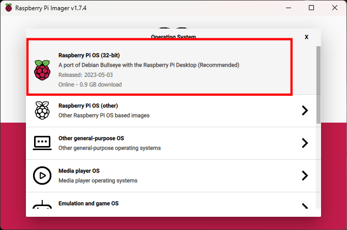
Open the Raspberry Pi OS Imager and click the “Choose OS” button In Windows, you will be prompted by the User Account Control (UAC) to continue. Select “Yes”
Select “Raspberry Pi OS (32-bit)
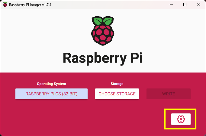
Click the button in the lower right corner, with the gear icon for the advanced settings
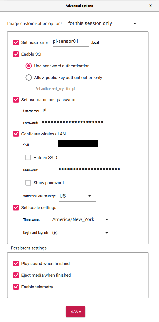
Set the hostname (optional but recommended)
Make certain that “Enable SSH” is checked and “Use password authentication” is selected
Change the password and optionally change the username
Enter the settings for your WiFi connection if not using ethernet
Optionally set time zone and keyboard layout
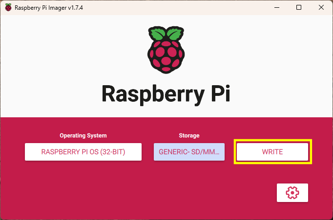
Once the options have been set, click the “Save” button
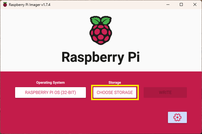
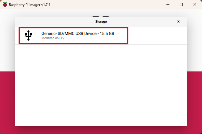
Click the “Choose Storage” button
Select the SD Card identified earlier. Make certain that this is the SD Card as all data will be wiped from the selected drive and will not be able to be recovered.
Click the “Write” button to write the OS image to the SD Card
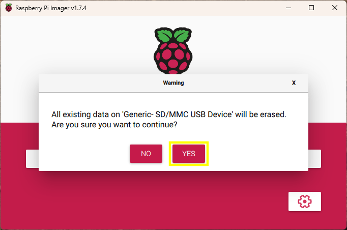
If you are absolutely certain that the correct SD Card has been selected and there is no data on the card that you wish to keep, click the “Yes” button.
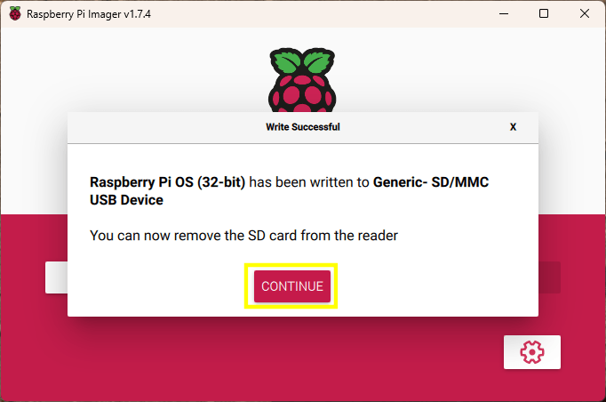
Once the image has been written to the SD Card, you may click the “Continue” button, close the Raspberry Pi OS Imager, and remove the SD Card from the PC, and insert it into the Raspberry Pi.
Once the SD Card is inserted into the Raspberry Pi, connect power to the Raspberry Pi
After a couple of minutes, open PuTTY on your PC and attempt to connect to the Raspberry Pi using the name provided in the advanced options of the Raspberry Pi OS Imager. In the example, “pi-sensor01.local” was used. In PuTTY, attempt to connect using the hostname provided in the image configuration. NOTE: If configuring another Raspberry Pi, do not use the same hostname.
Click the “Open” button after entering the hostname
You may see a PuTTY Security Alert if it is the first time connecting to the Raspberry Pi. If so, click the “Accept” button.
Once connected, enter the username and password that was entered in the advanced settings fo the the Raspberry Pi OS Imager.
Open the Raspberry Pi Configuration Tool by entering the following command: sudo raspi-config
Select option 3, Interface Options, and press the Enter key
Select option I3, VNC, and press the Enter key
Select Yes, to enable VNC Server, and press the Enter key
Select OK, and press the Enter key
Repeat the steps above to enable the Serial Port and any other interfaces, such as SPI and I2C that may be needed.
Check if there are any other options that you may want to set or execute. Some useful options are Advanced Options > Expand Filesystem and Update.
When done making changes, select Finish to exit the configuration tool.
If you selected Expand Filesystem, you may want to restart the Raspberry Pi by issuing the following command: sudo reboot now
VNC Viewer
Check that we are able to connect the Raspberry Pi Desktop using VNC Viewer.
Open VNC Viewer and connect to the hostname for the Raspberry Pi
If this is the first time you are connecting the Raspberry Pi, you will see an Identity Check dialog. Click the “Continue” button.
Enter the Raspberry Pi username and password, then click the “OK” button.
If everything went correctly, you will be presented with the Raspberry Pi desktop.
Screen Capture of the PyPortal Event Countdown Clock
Some big updates to the software for the modified PyPortal Event Countdown Clock. The UI was changed and several features added. It also seems to be more stable as it does not lock-up randomly. Let’s get into the changes.
Header and Footer status bars display information
Header
Temperature
Touch to change between Fahrenheit and Celsius
Time
Touch to change between 24 hour and 12 hour formats
Network Strength
Footer
Brightness
Touching the left side of the footer, dims the display backlight
Touching the right side of the footer, increases the brightness of the display backlight
Touching the middle of the footer, returns to auto brightness of the display backlight
Event of the number of events
Change the event displayed by touching the left of the display to show previous event or the right side to advance to the next event.
If an event has passed more than a day ago, they will be removed from the list of events and no longer displayed
The events do not need to be in order in the JSON file. They are sorted when they are loaded from the SD Card with the soonest event being displayed first.
Demo of the PyPortal Event Countdown Clock Mods
Noticed that the temperature was several degrees too high. This was due to the ADT7410 being too close to devices generating heat. I removed the ADT7410 and placed it on a small board and added a PH2 JST connector so it may be plugged into the I2C socket. This resulted in much more usable temperature reading.
ADT7410 Temperature Sensor moved to a separate board.
Adafruit PyPortal Titano
I just purchased an Adafruit PyPortal Titano, Product ID: 4444, to test out the software and see about allowing the software to be used on different sized screens. The Titano, has a 480×320 screen verses 320×240 of the PyPortal, Product ID: 4116.
The PyPortal Titano that I received had CircuitPython 5 installed, so the first order of business was to install CircuitPython 8. I started by going to the PyPortal CircuitPython Guide on Learn.Adafruit.
Double click the reset button on the back of the Titano board and make certain the RGB LED turns green. If is is not green, try again.
Copy the file to the PORTALBOOT drive that shows on your PC NOTE: Do not be concerned that the preinstalled demo no longer works. The library files are different for different versions.
Download the CircuitPython 8 library files from https://circuitpython.org/libraries NOTE: This step is optional as the required libraries are in the GitHub project files
Unzip the files and copy the files in the PyPortal folder to the PyPortal Titano
The PyPortal Titano will restart and the images will change between “Connecting to the Internet” and “Failed to Connect”. The images will not take up the full screen due to the difference in resolution. (Until the code is modified.) The reason it is not connecting is we need add files to an SD Card and put that into the PyPortal Titano.
Copy the files in the SD_Card folder, from GitHub, and paste them into the root of a micro SD Card.
While the SD Card is still in you PC, double click on the index.html file to open the configuration utility.
You may choose to load the config.json file on the card or start creating a new file from scratch by adding new events.
Once you are satisfied with the events, click on the “Secrets” tab and enter your Wi-Fi settings, Timezone, and Adafruit IO Account information.
Once done, click the “Save JSON File” button and save it to the SD Card as config.json.
Remove the card from the PC and insert it into the PyPortal Titano.
Click the reset button on the back of the PyPortal Titano.
If everything was done correctly, you can anticipate that the events will be displayed on the screen
The application is in the upper left corner of the screen with space to the right and bottom.
You may notice from the image of the PyPortal Titano screen, the temperature is not displayed as the PyPortal Titano does not have the ADT7410 Temperature Sensor.
The next step will be to see how to detect the screen size or make it a setting in the config.json file.
I recently purchased an Adafruit PyPortal and looked at using John Park’s project PyPortal Event Countdown Clock project. It was fairly easy to get it up an running but switching from CircuitPython 4 to 8, proved to cause a bit of a challenge, not with the code, but with the libraries. Some were moved from one file to multiple files in one folder but eventually, I got it all sorted out.
I plan to use the PyPortal on an upcoming cruise, which lead me to some ideas of how to change the code to make it a bit more useful and easier to change events. Below is a list of some of the ideas to be implemented.
(Implemented) Allow for multiple events to be tracked
(Implemented) Use touch to change which event is being displayed
(Implemented) Add title and subtitle to the display
Load the events and event images from an SD Card
Use a JSON file
Create a webpage to easily modify the JSON
If possible, add the WiFi information to the config file
Add a clock option and easily switch between countdown and clock
Dim or turn off the backlight if the room is dark
Ignore events that have passed (Date is not today but in the past)
The first step was to add multiple events and add touch capability to allow moving back and forth through the events. Adding multiple events was not difficult. A new class files was added for event objects and a list was created to hold them. Next was to add touch and split the screen in half with a 20 pixel dead zone in the middle so that touching the left side would take you to the previous event and touching the right side would move to the next event. It was also necessary to add a variable to track the last index so we would know when to load the selected event.
Touch zones on PyPortal 320×240 screen
event.py
import time


class event:
    def __init__(self, title, subtitle, year, month, day, hour, minute, imageCountDown, imageEventDay, forecolor=0xF0C810):
        self.title = title
        self.subtitle = subtitle
        self.forecolor = forecolor
        self.year = year
        self.month = month
        self.day = day
        self.hour = hour
        self.minute = minute
        self.date = time.struct_time((year, month, day,
                                      hour, minute, 0,  # we don't track seconds
                                      -1, -1, False))  # we dont know day of week/year or DST
        self.imageCountDown = imageCountDown
        self.imageEventDay = imageEventDay
code.py
# SPDX-FileCopyrightText: 2019 Limor Fried for Adafruit Industries
#
# SPDX-License-Identifier: MIT

"""
This example will figure out the current local time using the internet, and
then draw out a countdown clock until an event occurs!
Once the event is happening, a new graphic is shown
"""
import time
import board
import busio
from adafruit_pyportal import PyPortal
from adafruit_bitmap_font import bitmap_font
from adafruit_display_text.label import Label
from analogio import AnalogIn
import adafruit_adt7410
import adafruit_touchscreen
from event import event

events = []

events.append(event("Day 1", "Barcelona, Spain",
              2023, 5, 29, 00, 00,
              "barcelona_background.bmp", "barcelona_event.bmp"))
events.append(event("Day 2", "Fun Day At Sea",
              2023, 5, 30, 00, 00,
              "funday_background.bmp", "funday_event.bmp"))
events.append(event("Day 3", "Málaga, Spain",
              2023, 5, 31, 00, 00,
              "countdown_background.bmp", "countdown_event.bmp"))
events.append(event("Day 4", "Gibraltar (UK)",
              2023, 6, 1, 00, 00,
              "countdown_background.bmp", "countdown_event.bmp"))
events.append(event("Day 5", "Lisbon, Portugal",
              2023, 6, 2, 00, 00,
              "countdown_background.bmp", "countdown_event.bmp"))
events.append(event("Day 6", "Fun Day At Sea",
              2023, 6, 3, 00, 00,
              "funday_background.bmp", "funday_event.bmp"))
events.append(event("Day 7", "Fun Day At Sea",
              2023, 6, 4, 00, 00,
              "funday_background.bmp", "funday_event.bmp"))
events.append(event("Day 8", "Fun Day At Sea",
              2023, 6, 5, 00, 00,
              "funday_background.bmp", "funday_event.bmp"))
events.append(event("Day 9", "Fun Day At Sea",
              2023, 6, 6, 00, 00,
              "funday_background.bmp", "funday_event.bmp"))
events.append(event("Day 10", "Fun Day At Sea",
              2023, 6, 7, 00, 00,
              "funday_background.bmp", "funday_event.bmp"))
events.append(event("Day 11", "Fun Day At Sea",
              2023, 6, 8, 00, 00,
              "funday_background.bmp", "funday_event.bmp"))
events.append(event("Day 12", "Fun Day At Sea",
              2023, 6, 9, 00, 00,
              "funday_background.bmp", "funday_event.bmp"))
events.append(event("Day 13", "Fun Day At Sea",
              2023, 6, 10, 00, 00,
              "funday_background.bmp", "funday_event.bmp"))
events.append(event("Day 14", "Fun Day At Sea",
              2023, 6, 11, 00, 00,
              "funday_background.bmp", "funday_event.bmp"))
events.append(event("Day 15", "Fun Day At Sea",
              2023, 6, 12, 00, 00,
              "funday_background.bmp", "funday_event.bmp"))
events.append(event("Day 16", "New York, New York",
              2023, 6, 13, 00, 00,
              "nyc_background.bmp", "nyc_event.bmp"))


# determine the current working directory
# needed so we know where to find files
cwd = ("/"+__file__).rsplit('/', 1)[0]
# Initialize the pyportal object and let us know what data to fetch and where
# to display it
pyportal = PyPortal(status_neopixel=board.NEOPIXEL,
                    default_bg=cwd+"/coming_soon.bmp")

big_font = bitmap_font.load_font(cwd+"/fonts/Helvetica-Bold-36.bdf")
big_font.load_glyphs(b'0123456789')  # pre-load glyphs for fast printing
title_font = bitmap_font.load_font(cwd+"/fonts/Arial-36.bdf")
subtitle_font = bitmap_font.load_font(cwd+"/fonts/Arial-20.bdf")

text_color = 0xFFFFFF
days_position = (big_font, 8, 207)
hours_position = (big_font, 110, 207)
minutes_position = (big_font, 220, 207)
title_position = (title_font, 8, 140)
subtitle_position = (subtitle_font, 8, 175)

text_areas = []
for pos in (days_position, hours_position, minutes_position, title_position, subtitle_position):
    textarea = Label(pos[0])
    textarea.x = pos[1]
    textarea.y = pos[2]
    textarea.color = text_color
    pyportal.splash.append(textarea)
    text_areas.append(textarea)

refresh_time = None

# Touchscreen setup
# ------Rotate 270:
screen_width = 240
screen_height = 320
ts = adafruit_touchscreen.Touchscreen(board.TOUCH_XL, board.TOUCH_XR,
                                      board.TOUCH_YD, board.TOUCH_YU,
                                      calibration=(
                                          (5200, 59000), (5800, 57000)),
                                      size=(screen_width, screen_height))

# ------------- Inputs and Outputs Setup ------------- #
light_sensor = AnalogIn(board.LIGHT)
try:
    # attempt to init. the temperature sensor
    i2c_bus = busio.I2C(board.SCL, board.SDA)
    adt = adafruit_adt7410.ADT7410(i2c_bus, address=0x48)
    adt.high_resolution = True
except ValueError:
    # Did not find ADT7410. Probably running on Titano or Pynt
    adt = None

event_index = 0
last_event_index = -1

while True:
    touch = ts.touch_point
    light = light_sensor.value

    if touch:
        # print(f"Touched x={ts.touch_point[0]}, y={ts.touch_point[1]}")
        if touch[0] < 150:
            event_index = event_index - 1
            if event_index < 0:
                event_index = len(events) - 1
        elif touch[0] > 170:
            event_index = event_index + 1
            if event_index > len(events) - 1:
                event_index = 0

    if event_index != last_event_index:
        pyportal.set_background(cwd + "/" + events[event_index].imageCountDown)
        text_areas[3].color = events[event_index].forecolor
        text_areas[3].text = events[event_index].title
        text_areas[4].color = events[event_index].forecolor
        text_areas[4].text = events[event_index].subtitle
        last_event_index = event_index

    # only query the online time once per hour (and on first run)
    if (not refresh_time) or (time.monotonic() - refresh_time) > 3600:
        try:
            print("Getting time from internet!")
            pyportal.get_local_time(False)
            refresh_time = time.monotonic()
        except RuntimeError as e:
            print("Some error occured, retrying! -", e)
            continue

    now = time.localtime()
    print("Current time:", now)
    remaining = time.mktime(events[event_index].date) - time.mktime(now)
    print("Time remaining (s):", remaining)
    if remaining < 0:
        # oh, its event time!
        pyportal.set_background(cwd + "/" + events[event_index].imageEventDay)
        while True:  # that's all folks
            pass
    secs_remaining = remaining % 60
    remaining //= 60
    mins_remaining = remaining % 60
    remaining //= 60
    hours_remaining = remaining % 24
    remaining //= 24
    days_remaining = remaining
    print("%d days, %d hours, %d minutes and %s seconds" %
          (days_remaining, hours_remaining, mins_remaining, secs_remaining))
    text_areas[0].text = '{:>2}'.format(days_remaining)  # set days textarea
    text_areas[1].text = '{:>2}'.format(hours_remaining)  # set hours textarea
    text_areas[2].text = '{:>2}'.format(mins_remaining)  # set minutes textarea

    # update every 10 seconds
    # time.sleep(10)
I wanted to see about connecting a Raspberry Pi Pico to a LillyGo TTGO T-Beam v1.1 device. I noticed that Meshtastic supports serial communications, so I decided to give it a go to see how it worked.
There are several serial modes but the ones that seem the most useful are TXTMSG and PROTO. First attempt will be with the TXTMSG Mode as that seems straight forward. Once the TXTMSG Mode is working, I will look into how to use the PROTO Mode.
Wiring
We need to connect the grounds between the two devices, then connect the transmit (TX) from one to the receive (RX) of the other device. Below is a table showing the connections used in my setup.
T-Beam
Pico
RX pin 13
TX pin 1 (GP0)
TX pin 14
RX pin 2 (GP1)
GND
GND
Wiring between T-Beam and Raspberry Pi Pico
Meshtastic Setup
Meshtastic firmware was installed using the Web Installer at https://flasher.meshtastic.org/. The T-Beam came with Meshtastic preinstalled. You may need to use another method to install the firmware if the Web Installer does not work.
Meshtastic Web Installer
T-Beam TEXTMSG Mode
Once Meshtastic has been installed on the T-Beam device and connected to the Android or Apple application, go to the Module Settings to setup the serial connection on the T-Beam device. The Module Settings is accessed by clicking on the kebab menu (aka three vertical dots menu) and selecting “Module Settings”.
Kebab MenuModule Settings menu item
Once the Module settings are displayed, scroll down to the “Serial Config” section and set the following items.
Serial enabled: turn on
RX: Set it to the T-Beam pin number for receive, which is 13 in my setup.
TX: Set it to the T-Beam pin number for transmit, which is 14 in my setup.
Serial baud rate: May leave it at the default setting or set it to “BAUD_38400”. I think it is best to set it as the default baud rate may change in other versions. I believe I read that it did change in the past.
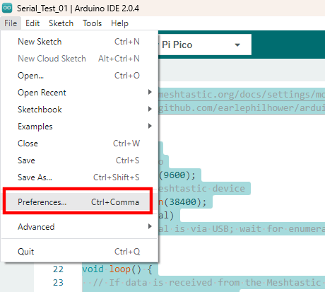
Arduino Preferences Menu ItemArduino IDE Preferences
Click the icon to the left of the “Additional boards manager URLs” entry. Add the URL to the a new line in the textbox and click the “OK” button.
Additional Boards Manager URLs
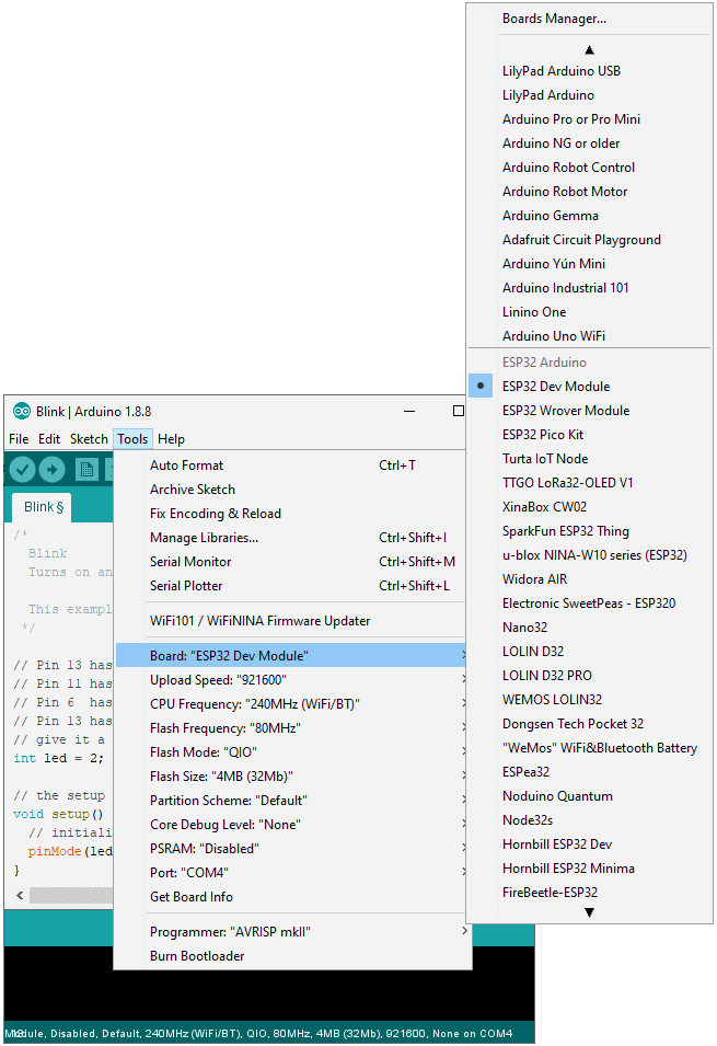
Open the boards manager by clicking on the boards manager icon, type “Pico” in the search textbox, and install the board, Raspberry Pi Pico/RP2040 by Earle F. Philhower, III.
Boards Manager
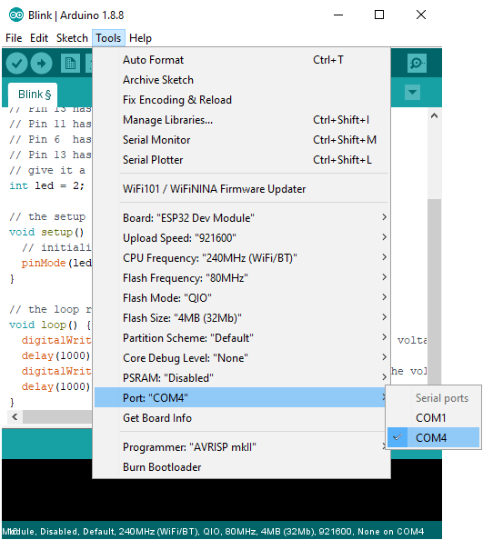
Once the board is installed, you may select it from the boards dropdown selection in the IDE, when the Pico is connected to the PC.
Raspberry Pi Pico selected in the boards drop-down list
/*
  Sample code to allow the Pico to act as a serial bridge between the PC and the Meshtastic device.

  Data sent to the Pico using the Arduino Serial Monitor, PuTTY, or other terminal software is sent
  to the Meshtastic device over the Pico UART0/Serial1 connection. Any data received from the Meshtastic
  device to the Pico is relayed to the PC over the Pico's serial over USB connection.

  REFERENCES:
    - https://meshtastic.org/docs/settings/moduleconfig/serial
    - https://github.com/earlephilhower/arduino-pico/discussions/210
*/

void setup() {
  // PC to Pico
  Serial.begin(9600);
  // Pico to Meshtastic device
  Serial1.begin(38400);
  while (!Serial)
    ;  // Serial is via USB; wait for enumeration
}

void loop() {
  // If data is received from the Meshtastic device, send it to the PC over the USB connection
  if (Serial1.available()) {
    String receiveMessage = Serial1.readString();
    Serial.print("Message received on Serial1 is:  ");
    Serial.println(receiveMessage);  // Send to serial monitor
  }

  // If data is received from the PC, send it to the Meshtastic Device
  while (Serial.available()) {
    int inByte = Serial.read();
    Serial1.write(inByte);
  }
}
Upload the code to the Raspberry Pi Pico. Once the code is loaded, open the serial monitor and type some text and hit enter. The message will be received on the other node(s).
Sending message from PCMessage received on other node
Sending a message from another node, will be received and shown in the serial terminal.
Sending message from another nodeReceiving message on PC
Now the simple TEXTMSG is working, we can try to get the PROTO working. The PROTO mode is interesting as it may be possible to configure the Meshtastic device, and query it for additional information. I will look into the PROTO Mode in the near future.
I’m once again revisiting the ATtiny85 and wanted to see how to load sketches through USB in addition to the ICSP connection. I ran into quite a few stumbling blocks so I want to capture what I found in hopes that it will help others.
I purchased a few things on eBay recently, including some ESP32s for $7.99 each from eBay seller, miniduino. I have not worked with the ESP32 but I know that it can work with the Arduino IDE and can run CircuitPython. I am familiar with the Arduino IDE so I wanted to get the ESP32 to work with the Arduino IDE so I can test them out and make certain that they work fine.
Doing a Google search on ESP32 and Arduino IDE returned many results which helped to get me going. The process for getting the ESP32 up and running is nearly the same as with the Teensy boards. The exception is that the Teensy boards have one nice executable to get things setup. The high-level steps to get ESP32 working with Arduino are the following.
Install the latest Arduino IDE if you do not already have it installed. (https://www.arduino.cc/)
Depending on your operating system, you may need to install the driver. I am running Windows 10 so I needed to install the driver for the Silicon Labs CP2102 from https://www.silabs.com/products/development-tools/software/usb-to-uart-bridge-vcp-drivers. BTW: The boards that I purchased have no markings on the CP2102 chip. I fear that the chips are counterfeit or a lower grade chip. The first one I tested works so I’ll keep my fingers crossed.
Once the driver was installed, I needed install the Arduino libraries for the ESP32 by cloning the GitHub repository at https://github.com/espressif/arduino-esp32. NOTE: A better way it to follow the “Installation instructions using Arduino IDE Boards Manager” instructions on the GitHub page.
Program the ESP32 with the blink example.
Load the blink example in the Arduino IDE and modify the example to use pin 2 for the led.
/*
  Blink
  Turns on an LED on for one second, then off for one second, repeatedly.

  This example code is in the public domain.
 */

// Pin 13 has an LED connected on most Arduino boards.
// Pin 11 has the LED on Teensy 2.0
// Pin 6  has the LED on Teensy++ 2.0
// Pin 13 has the LED on Teensy 3.0
// give it a name:
int led = 2;

// the setup routine runs once when you press reset:
void setup() {
  // initialize the digital pin as an output.
  pinMode(led, OUTPUT);
}

// the loop routine runs over and over again forever:
void loop() {
  digitalWrite(led, HIGH);   // turn the LED on (HIGH is the voltage level)
  delay(1000);               // wait for a second
  digitalWrite(led, LOW);    // turn the LED off by making the voltage LOW
  delay(1000);               // wait for a second
}
Pick the “ESP32 Dev Module” from the “Boards” menu option
Select the COM port for your board
Upload the program to the ESP32 by clicking the upload button then press and hold the boot button on the ESP32 board. You may release the button once the upload starts.


You must be logged in to post a comment.