Testing projects in real world situations can help uncover issues that we wish would have been discovered earlier. One such example was with my Speech Timer Project.
I traveled to Binghamton, NY so I could attend my family reunion and decided to arrive early to attend the Morning Knights Toastmasters meeting in-person. I brought along my Speech Timer to try it out at the meeting. Before the meeting even started, I ran into an issue. The clock connects to the internet to get the time to set the real time clock (RTC). I knew this but thought the clock would still operate as the RTC does not need to be set for the speech timer to work. The configuration is set for my home network so I knew it would not connect to the internet at the meeting location. I pressed the button on the remote to activate the timer function and nothing happened. I ended up tucking the clock back into my backpack. I’ll need to edit the code and run some tests to make absolutely certain that it will work when it cannot connect to the internet.
This lesson shows how important it is to test our projects in a variety of situations. I believe I have tested this scenario before, so I will need to make certain that I can recreate it with the current code base, then move on from there.
Wiring diagram for Raspberry Pi boards connected to LilyGo T-Beam devices
In this part of the Meshtastic with Raspberry Pi (Serial) series, we will be writing some code to test the connection, then adding to our code to send sample data. When sending data, we will format the message to allow us to reject data if it is not formatted correctly and do some simple error detection.
On the Raspberry Pi, open a terminal window or use PuTTY to run the following command. sudo nano /boot/cmdline.txt
Comment out or delete the “console=serial0,115400” in the line.
Once the cmdline.txt has been modified, restart the Raspberry Pi.
NOTES: If the console=serial0,115400 is missing, you skipped enabling the serial port from the raspi-config tool. Look back at the earlier posts in this series for instructions on how to enable the serial port. It is also possible that the baud rate in the command is something other than 115400 so you may see a different baud rate, which is fine, but you will need to remove that argument from the file.
Test Program
Now that the serial port is properly configured, we can write a simple program and test the T-Beam connection to the Raspberry Pi. On both Raspberry Pi boards, create a uart.py file with the following code.
'''
UART communication on Raspberry Pi using Python
http://www.electronicwings.com
'''
import serial
from time import sleep

ser = serial.Serial ("/dev/ttyS0", 38400)    #Open port with baud rate
while True:
    raw_data = ser.read()              #read serial port
    sleep(0.03)
    if raw_data:
        data_len = ser.inWaiting()
        raw_data += ser.read(data_len)              #read serial port
        received_data = str(raw_data, "utf-8")
        print (received_data)                   #print received data
The code will listen for data on the serial port and will print the received data in the terminal window. Run the code on both Raspberry Pi boards by typing the following command. sudo python uart.py
On the Android device, open the Meshtastic application and type a message and press the send button.
The message will be displayed in the terminal window of the receiving Raspberry Pi device.
Sample code sending and receiving data
Before using the following example, it is suggested to change the serial configuration to “Simple” and creating an additional channel named “serial”. Screenshots were taken of the Meshtastic application and placed into a Google Album. Refer to the album if you have any questions regarding what configuration values were used for this example.
The sample code will send CPU Temperature data twice per minute. Below are a few notes/requirements.
The data will be sent as JSON.
The data will be contained in a Python Dictionary with string values for the keys. Sample keys:
t: Time in UTC ISO 8601 format without milliseconds
nam: The host name of the Raspberry Pi
cput: CPU Temperature in degrees Celsius
Float values will be sent as formatted strings with the precession required for the application. As an example, temperature will be sent with two decimal values.
The total length of the message shall not exceed 200 bytes. In practice, it should be kept well below 200 bytes. This requires that the keys for the key value pairs to be kept short.
Example Code:
The following example code was written to meet the above requirements.
'''
- References -
--------------
ISO 8601
    https://pynative.com/python-iso-8601-datetime/
UART communication on Raspberry Pi using Pyhton
    http://www.electronicwings.com
'''

import serial
import time
from datetime import datetime, timezone
import re
import socket
import json

def get_temp():
    with open('/sys/class/thermal/thermal_zone0/temp', 'r') as infile:
        return float(infile.read()) * 1e-3

# Open port with baud rate
ser = serial.Serial("/dev/ttyS0", 38400)
# Set the start time in the past so that the first data point will be sent at the startF
start = time.time() - 600
# Create a variable for the received data.
received_data = ""
# Flag for knowning if the error for T-Beam being disconnected has been displayed
no_serial = False

try:
    while True:
        data_len = 0
        data_len = ser.in_waiting
        utc_dt = datetime.now(timezone.utc).replace(microsecond=0)

        if data_len > 0:
            raw_data = ser.read(data_len)  # read serial port
            try:
                received_data += str(raw_data, "utf-8")
                x = re.search("\{.*\}", received_data)
                if x:
                    # PuTTY changes tab characters to spaces so we will use the pipe symbol
                    # print(F"{utc_dt.isoformat()}\tRECV\t{x[0]}")
                    print(F"{utc_dt.isoformat()}|RECV|{x[0]}")
                    received_data = ""
                if no_serial:
                    no_serial = False
            except UnicodeDecodeError:
                received_data = ""
                if not no_serial:
                    print("ERROR: The serial connection may be down")
                    no_serial = True

        if time.time() - start > 30:
            start = time.time()
            temp = get_temp()
            dat = {
                "t": utc_dt.isoformat(),
                "nam": socket.gethostname(),
                "cput": F"{temp:0.2f}",
            }
            if len(json.dumps(dat)) < 200:
                ser.write(bytes(json.dumps(dat), "utf-8"))
                # PuTTY changes tab characters to spaces so we will use the pipe symbol
                # print(F"{utc_dt.isoformat()}\tSENT\t{json.dumps(dat)}")
                print(F"{utc_dt.isoformat()}|SENT|{json.dumps(dat)}")
            else:
                print(
                    F"ERROR: Data length is greater than 200 bytes (length={len(json.dumps(dat))})")

except KeyboardInterrupt:
    print("\r\nExiting")
# finally:
#   GPIO.cleanup()
Below is the output from both Raspberry Pi boards running the code with the same T-Beam Meshtastic settings.
An Excel workbook was put together to check the delay from transmit and receive as well as identifying packets being received out of order. Previous runs with slightly different code did contain out of order packets so it should not be assumed that packets will be received in order. Below is the Check.xlsx file that you may download.
Below are some statistics from the Check.xlsx Excel Workbook with data produced from 27 minutes runtime of the sample code.
pi-sensor01
Receive Delay (hh:mm:ss)
Min: 00:00:07
Max: 00:04:12
Average: 00:01:28
Median: 00:00:57
Data Received out of order: 0
Data Points
Total: 104
Sent: 56
Received: 48
Sent Packets Received by pi-sensor01:
Received: 55
Not Received: 1
Percent of Packets Received: 98.21%
pi-sensor02
Receive Delay (hh:mm:ss)
Min: 00:00:07
Max: 00:01:35
Average: 00:00:23
Median: 00:00:15
Data Received out of order: 1
Data Points
Total: 111
Sent: 56
Received: 55
Sent Packets Received by pi-sensor01:
Received: 48
Not Received: 8
Percent of Packets Received: 85.71%
Going Further
This is the end of this series at least for now. It was put together to provide some information with one way to send data between two Raspberry Pi devices using serial communications. There are other ways to send data using the serial port. One of the more interesting ways may be using the PROTO mode for the Meshtastic serial port. It looks like using the PROTO mode may allow for the code to setup and configure the Meshtastic device. If that is the case, it may provide much more control and standardization across connections. (Meshtastic Serial Port Configuration)
Another area to look into is how to improve the successful delivery of messages in a timely manor. It may be sending messages every 30 seconds was too fast and flooded the available channels. It may also be possible that the store and forward setting was misunderstood and caused message flooding on the channel. The devices may have been too close together to provide reliable communications. All of these things and others could be looked into to see if it is possible to create more reliable communications.
Wiring diagram for Raspberry Pi boards connected to LilyGo T-Beam devices
In this part of the Meshtastic with Raspberry Pi (Serial) series, we will be installing Meshtastic to the LilyGo T-Beam devices. We will then create a Meshtastic Channel on one LilyGo T-Beam and replicate the channel to the other LilyGo T-Beam. We will then wire the Raspberry Pi and LilyGo T-Beam devices.
Install Meshtastic Firmware on the LilyGo T-Beam devices
Firmware Version: Select the latest version. NOTE: May want to install latest beta version if you want the most stable version available.
Update or reinstall: Either option is fine. A reinstall may wipe out any settings that you have configured on the device but may be the best option for the first installation.
Click the “CONNECT” button
Select the serial port that the T-Beam is connected to. If you are uncertain, you may open the Windows Device Manager and look at Ports (COM & LPT), then look for “USB-Enhanced-SERIAL CH9102” or similar device to find the serial port.
Click “INSTALL TBEAM”
Click “INSTALL”
You will see the progress as it installs the firmware.
When the installation is complete, click “NEXT”
You may then click the X in the device dashboard to close the dashboard.
Repeat the steps for the other T-Beam, then close the browser.
Configure T-Beam and Create Channel
Using a mobile phone, tablet, or PC, open the Meshtastic App or Web Client. The following examples will show the Web Client and Android App.
It is best to use the Android application to configure the T-Beam device. The instructions provided here for the Web Browser are incomplete as I could not determine how to set some of the options that I know are available in the Android Application. These instructions are provided to demonstrate how to access the configuration from the web browser.
With the LilyGo T-Beam connected to the PC, open a browser and navigate to https://client.meshtastic.org/. Click the “New Connection” button.
The “Connect New Device” dialog is shown. Click the “New device” button.
Select the T-Beam device from the list of devices and click the “Connect” button.
Click the device from the device list.
The selected device will turn gray to show that it is selected. Click the X in the top right corner of the “Connect New Device” dialog to close the dialog box.
Android App
If the Meshtastic application is not already installed, go to the Play Store and search for an install the Meshtastic App.
Open the Meshtastic Application and click the gear icon in the top toolbar on the right, then click the “+” in the lower right corner to add a new Meshtastic device.
On the T-Beam device, look for the device name on the LCD screen.
In the Meshtastic App, select the device name that matches the name on the T-Beam LCD Screen, in the list of available devices.
The T-Beam device will display a Bluetooth pin on the LCD Screen.
Enter the Pin in the Bluetooth pairing request screen and click “OK”.
Next, we need to set the region by clicking on the region dropdown. NOTE: Make certain that the correct device is selected.
Select your region from the list. My region is “US”, so that is what I selected.
The selected region will be displayed in the application and the T-Beam device will reboot.
Once the device reboots, you may enter a name if you like. Do not move off this screen right away or the name may not stick. You may find that you need to reenter the name a few times before it is saved.
Click on the hamburger menu in the upper right corner and select “Radio configuration”.
Click on “Serial” from the “Radio configuration” menu.
Enter the settings for the Serial Port, then click the “Send” button.
Serial enabled: Turn on
RX: Pin 13
TX: Pin 14
Serial baud rate: Selected 38400 baud but may select different rate. Make certain this matches when writing code on the Raspberry Pi.
Serial mode: TEXTMSG
If you want a private channel, setup the channel on one device, then scan the QR Code on the other devices in the Mesh. I will not go over setting up a channel. For more information on setting up a channel, go to Meshtastic’s Channel Configuration page.
Wire Everything Up
The connection between the Raspberry Pi and the T-Beam device only requires three wires. A wire for the ground and two for the serial connection. The serial connection will cross the transmit (TX) and receive (RX) wires so that the TX from the Raspberry Pi is connected to the T-Beam RX and the Raspberry Pi RX will connect to the T-Beam TX. Below is a diagram showing these connections.
Wiring diagram for Raspberry Pi board connected to LilyGo T-Beam device
Wiring diagram for Raspberry Pi boards connected to LilyGo T-Beam devices
In Part I, we installed the Raspberry Pi OS and connected to the Raspberry Pi using PuTTY and VNC from another PC. In Part II, we will install Visual Code on the Raspberry Pi to allow us to code directly on the Raspberry Pi using a modern IDE.
It is not required to install Visual Studio Code. There are several options for writing programs and running them on the Raspberry Pi. It is possible to simply use the Text Editor on the desktop, Nano or VI from the terminal, or use an editor on the PC and transfer files using WinSCP.
Installing Visual Studio Code
The first thing to note is that the Chromium web browser is not going to work well on older Raspberry Pi boards. I am using a Raspberry Pi 3, so it is necessary to open a terminal and run the following command to launch the Dillo web browser: dillo
Clicking on the .deb Arm32 link does nothing as the link is using JavaScript to download the correct file. We will need to get the installation package from our PC and move it to the Raspberry Pi.
On the PC, navigate to https://code.visualstudio.com/download and click the .deb Arm32 link to download the installation package. Save it to a known location and remember where you saved it.
Open WinSCP and connect to the Raspberry Pi.
If it is the first time connecting to the Raspberry Pi, you will see a Warning dialog. Click “Yes” to continue.
Once connected, in the right pane of the WinSCP application, navigate to the desktop folder on the Raspberry Pi and in the left pane, navigate to the location of Visual Studio Code installation package on your PC. Once the locations have been selected, you may click and drag the installation package from the PC to the Raspberry Pi.
Once the package has been transferred, switch to VNC Viewer and you will see the file on your desktop.
Right-click on the installation package and select “Package Install” from the context menu.
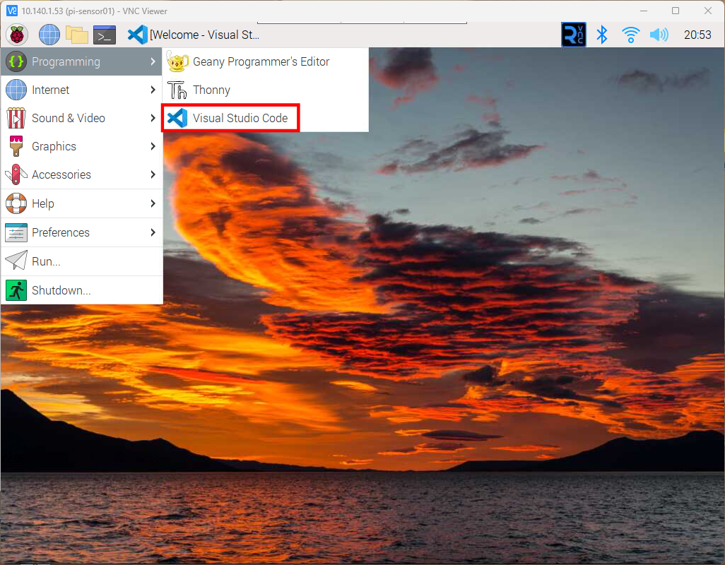
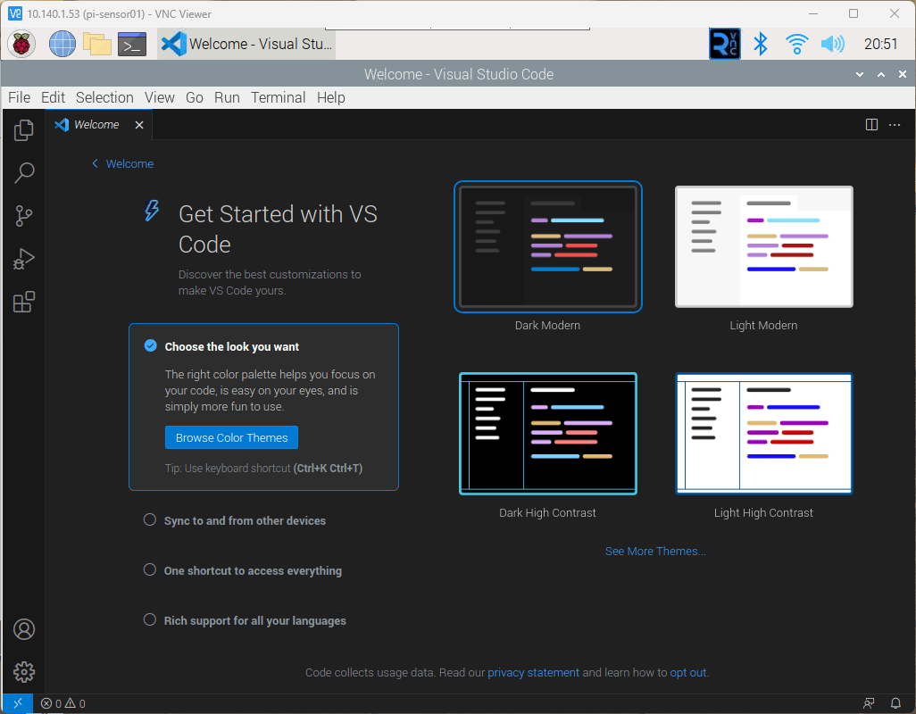
Once the installation completes, you may launch Visual Studio Code from the menu by navigating to Programming > Visual Studio Code.
NOTE: You may delete the Visual Studio Code installer from the desktop if you wish.
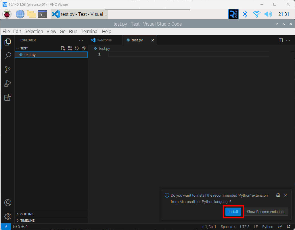
I like to use the Explorer, the top icon on the left toolbar, to open a folder. From there, I may create files and folders for the project. In the screenshot below, I have created a folder named “Test” in my home folder and added a file named “test.py”. Once I created the file, Visual Studio Code recognized that I created a Python file and prompted me to install the Python language extension.
Wiring diagram for Raspberry Pi boards connected to LilyGo T-Beam devices
In this post, I will step through getting Linux installed on a Raspberry Pi with an overview of different installations, and detailed setup on a headless installation. I will then move into connecting the Raspberry Pi to a LilyGo T-Beam device with Meshtastic Firmware, with the connection to the Raspberry Pi using a Serial Connection. Connecting one or more sensors to the Raspberry Pi, and finally sending that data to another Raspberry Pi connected to a LilyGo T-Beam.
Before Installing Linux on Raspberry Pi
There are several options for installing Linux on the Raspberry Pi. The first question to answer is, which distribution to use? There are several different distributions available for the Raspberry Pi boards. A comprehensive list of distributions available may be found at https://elinux.org/RPi_Distributions. The distribution that I will be using is Raspberry Pi OS by Raspberry Pi.
The next question to answer is do we want a desktop or do we wish to run in headless mode? Installing a desktop is helpful if we wish to use the Raspberry Pi as a regular computer with a nice user interface. Installing a desktop does require more resources but makes the Raspberry Pi more useful if we wish to connect it to a display and keyboard or use VNC from another machine.
A headless mode installation is best if we only need to work from the terminal (command line) and/or we want more resources for running applications to monitor sensors or server up web pages or application program interfaces (API).
The last question to ask is what peripherals and options do we need to have configured? We know we will want the serial interface enabled, since that will be used to communicate to the LilyGo T-Beam devices. Depending on the sensors that we wish to use, we may want to enable the I2C interface.
Another option we will want is to be able to control the Raspberry Pi from another machine as we do not want to connect a monitor, keyboard, and mouse. We will need to enable SSH and VNC to allow control from another machine.
Below is a list of our installation options that we will configure.
Distribution: Raspberry Pi OS
Mode: Desktop
Enable SSH
Enable VNC
Enable Serial
Enable I2C
We have a couple of ways to enable the above configuration but we will configure all of these options from the Raspberry Pi Imager as it makes this relatively easy and quick. The toughest part is determining what the IP Address is of the Raspberry Pi when it boots up.
Required software on the Windows, Linux, or Apple PC
There is some software that we need to have on the PC in order to install the Raspberry Pi OS and control it from the PC. If the listed software does not support your operating system, look for a similar application for your operating system.
Insert an SD Card in your PC and note the drive letter. Make certain that the SD Card does not have anything that you wish to keep as the card will be wiped, so your information will be gone.
Open the Raspberry Pi OS Imager and click the “Choose OS” button In Windows, you will be prompted by the User Account Control (UAC) to continue. Select “Yes”
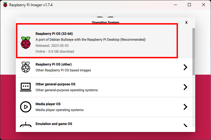
Select “Raspberry Pi OS (32-bit)
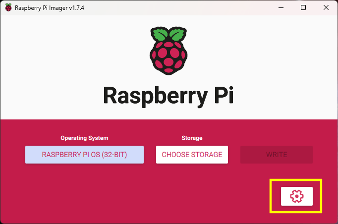
Click the button in the lower right corner, with the gear icon for the advanced settings
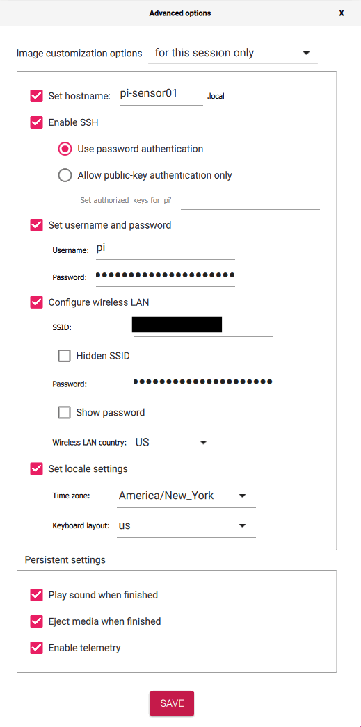
Set the hostname (optional but recommended)
Make certain that “Enable SSH” is checked and “Use password authentication” is selected
Change the password and optionally change the username
Enter the settings for your WiFi connection if not using ethernet
Optionally set time zone and keyboard layout
Once the options have been set, click the “Save” button
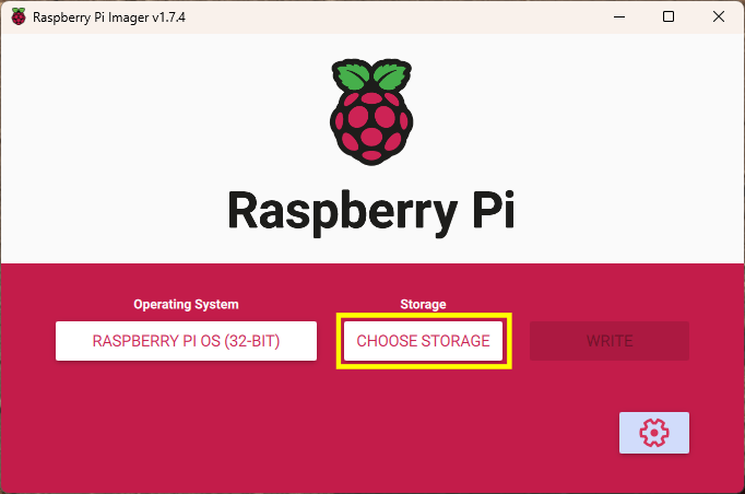
Click the “Choose Storage” button
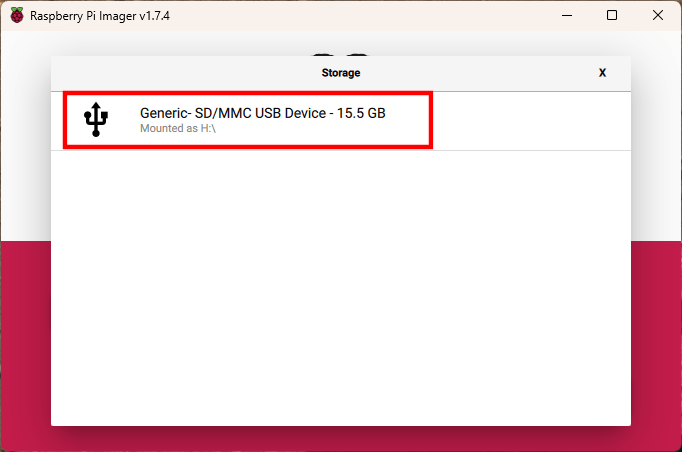
Select the SD Card identified earlier. Make certain that this is the SD Card as all data will be wiped from the selected drive and will not be able to be recovered.
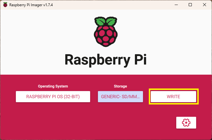
Click the “Write” button to write the OS image to the SD Card
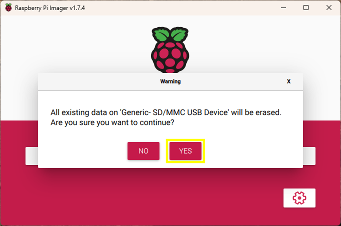
If you are absolutely certain that the correct SD Card has been selected and there is no data on the card that you wish to keep, click the “Yes” button.
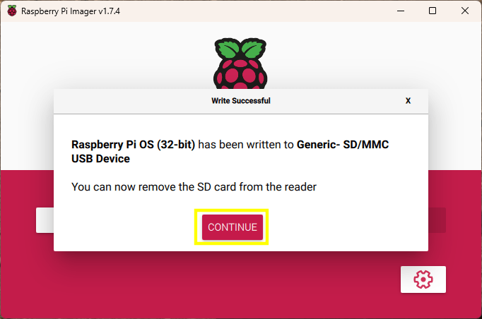
Once the image has been written to the SD Card, you may click the “Continue” button, close the Raspberry Pi OS Imager, and remove the SD Card from the PC, and insert it into the Raspberry Pi.
Once the SD Card is inserted into the Raspberry Pi, connect power to the Raspberry Pi
After a couple of minutes, open PuTTY on your PC and attempt to connect to the Raspberry Pi using the name provided in the advanced options of the Raspberry Pi OS Imager. In the example, “pi-sensor01.local” was used. In PuTTY, attempt to connect using the hostname provided in the image configuration. NOTE: If configuring another Raspberry Pi, do not use the same hostname.
Click the “Open” button after entering the hostname
You may see a PuTTY Security Alert if it is the first time connecting to the Raspberry Pi. If so, click the “Accept” button.
Once connected, enter the username and password that was entered in the advanced settings fo the the Raspberry Pi OS Imager.
Open the Raspberry Pi Configuration Tool by entering the following command: sudo raspi-config
Select option 3, Interface Options, and press the Enter key
Select option I3, VNC, and press the Enter key
Select Yes, to enable VNC Server, and press the Enter key
Select OK, and press the Enter key
Repeat the steps above to enable the Serial Port and any other interfaces, such as SPI and I2C that may be needed.
Check if there are any other options that you may want to set or execute. Some useful options are Advanced Options > Expand Filesystem and Update.
When done making changes, select Finish to exit the configuration tool.
If you selected Expand Filesystem, you may want to restart the Raspberry Pi by issuing the following command: sudo reboot now
VNC Viewer
Check that we are able to connect the Raspberry Pi Desktop using VNC Viewer.
Open VNC Viewer and connect to the hostname for the Raspberry Pi
If this is the first time you are connecting the Raspberry Pi, you will see an Identity Check dialog. Click the “Continue” button.
Enter the Raspberry Pi username and password, then click the “OK” button.
If everything went correctly, you will be presented with the Raspberry Pi desktop.
The Raspberry Pi Pico may be programmed in the Arduino IDE. There are three board libraries available but I found that the one written by Earle F. Philhower, III works best. Below are the steps that I took to get the example blink sketch loaded on the Raspberry Pi Pico.
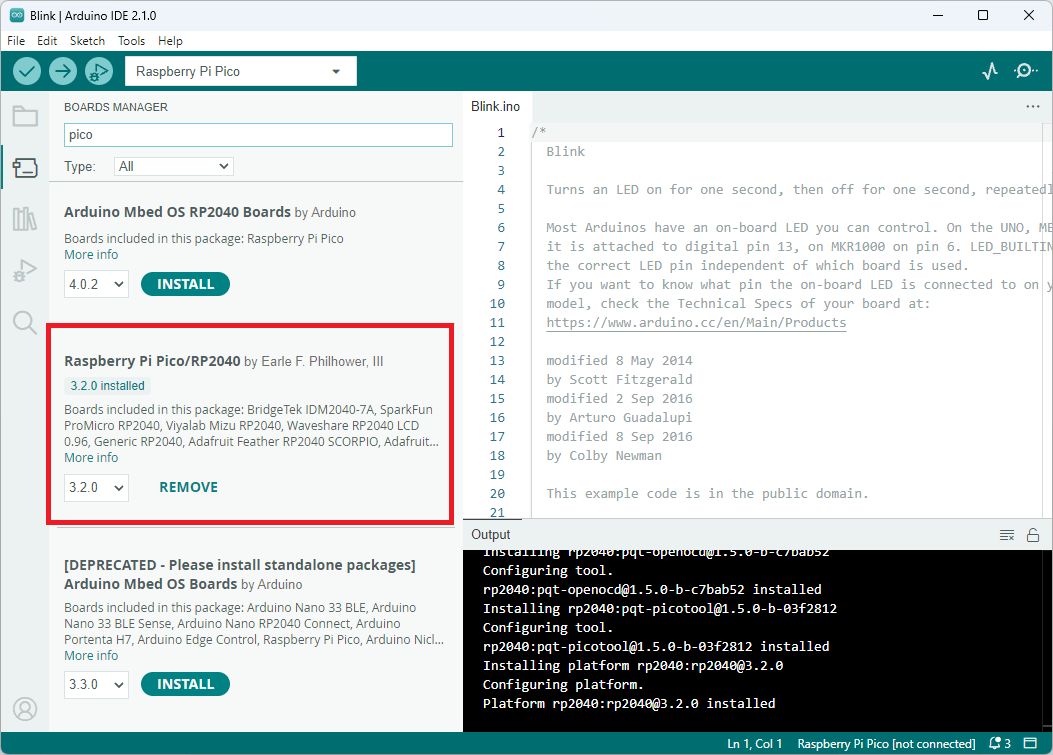
In the Arduino IDE, open the Boards Manager
Type “Pico” in the search box
If the “Arduino Mbed OS RP2040 Boards” is installed, click the “Remove” button to uninstall it
If the “Raspberry Pi Pico/RP 2040” is not installed, click the “Install” button to install it
Connect the Raspberry Pi Pico to the PC through the USB Port
In the Arduino IDE menu, select the “Raspberry Pi Pico” board by going to Tools > Board > Raspberry Pi RP2040 Boards(3.2.0) (in Sketchbook) > Raspberry Pi Pico
In the Arduino IDE menu, select Tools > Port from the menu
If this is the first time connecting the Raspberry Pi Pico to the PC, select UF2 Board
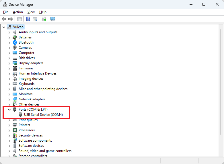
If this is not the first time, then a list of COM Ports are available. Open the Device Manager to see the available COM Ports and determine which one is the Pico board. You may unplug the Pico Board, wait for the Device Manager to refresh with one less COM Port, then plug the Pico board back in. Note, which new COM Port appears, that will be the one to select in the Arduino IDE.
Open the example “Blink” sketch from the menu File > Examples > 01. Basics > Blink
Click the “Upload” button in the Arduino IDE to load the sketch onto the Pico board NOTE: You may see several warnings about whitespace. These warnings may be ignored
You should see the LED on the Pico board flashing once the sketch is uploaded
Hopefully, this gets you up and running. It is always a good idea to run the example blink program first when configuring a new board. It lets you know right away if things are working as expected. Once that works, then move onto your code.
I wanted to see about connecting a Raspberry Pi Pico to a LillyGo TTGO T-Beam v1.1 device. I noticed that Meshtastic supports serial communications, so I decided to give it a go to see how it worked.
There are several serial modes but the ones that seem the most useful are TXTMSG and PROTO. First attempt will be with the TXTMSG Mode as that seems straight forward. Once the TXTMSG Mode is working, I will look into how to use the PROTO Mode.
Wiring
We need to connect the grounds between the two devices, then connect the transmit (TX) from one to the receive (RX) of the other device. Below is a table showing the connections used in my setup.
T-Beam
Pico
RX pin 13
TX pin 1 (GP0)
TX pin 14
RX pin 2 (GP1)
GND
GND
Wiring between T-Beam and Raspberry Pi Pico
Meshtastic Setup
Meshtastic firmware was installed using the Web Installer at https://flasher.meshtastic.org/. The T-Beam came with Meshtastic preinstalled. You may need to use another method to install the firmware if the Web Installer does not work.
Meshtastic Web Installer
T-Beam TEXTMSG Mode
Once Meshtastic has been installed on the T-Beam device and connected to the Android or Apple application, go to the Module Settings to setup the serial connection on the T-Beam device. The Module Settings is accessed by clicking on the kebab menu (aka three vertical dots menu) and selecting “Module Settings”.
Kebab MenuModule Settings menu item
Once the Module settings are displayed, scroll down to the “Serial Config” section and set the following items.
Serial enabled: turn on
RX: Set it to the T-Beam pin number for receive, which is 13 in my setup.
TX: Set it to the T-Beam pin number for transmit, which is 14 in my setup.
Serial baud rate: May leave it at the default setting or set it to “BAUD_38400”. I think it is best to set it as the default baud rate may change in other versions. I believe I read that it did change in the past.
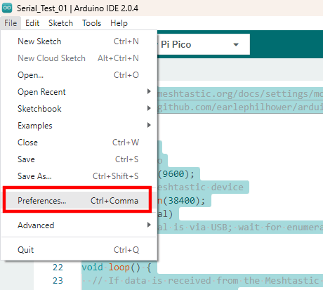
Arduino Preferences Menu ItemArduino IDE Preferences
Click the icon to the left of the “Additional boards manager URLs” entry. Add the URL to the a new line in the textbox and click the “OK” button.
Additional Boards Manager URLs
Open the boards manager by clicking on the boards manager icon, type “Pico” in the search textbox, and install the board, Raspberry Pi Pico/RP2040 by Earle F. Philhower, III.
Boards Manager
Once the board is installed, you may select it from the boards dropdown selection in the IDE, when the Pico is connected to the PC.
Raspberry Pi Pico selected in the boards drop-down list
/*
  Sample code to allow the Pico to act as a serial bridge between the PC and the Meshtastic device.

  Data sent to the Pico using the Arduino Serial Monitor, PuTTY, or other terminal software is sent
  to the Meshtastic device over the Pico UART0/Serial1 connection. Any data received from the Meshtastic
  device to the Pico is relayed to the PC over the Pico's serial over USB connection.

  REFERENCES:
    - https://meshtastic.org/docs/settings/moduleconfig/serial
    - https://github.com/earlephilhower/arduino-pico/discussions/210
*/

void setup() {
  // PC to Pico
  Serial.begin(9600);
  // Pico to Meshtastic device
  Serial1.begin(38400);
  while (!Serial)
    ;  // Serial is via USB; wait for enumeration
}

void loop() {
  // If data is received from the Meshtastic device, send it to the PC over the USB connection
  if (Serial1.available()) {
    String receiveMessage = Serial1.readString();
    Serial.print("Message received on Serial1 is:  ");
    Serial.println(receiveMessage);  // Send to serial monitor
  }

  // If data is received from the PC, send it to the Meshtastic Device
  while (Serial.available()) {
    int inByte = Serial.read();
    Serial1.write(inByte);
  }
}
Upload the code to the Raspberry Pi Pico. Once the code is loaded, open the serial monitor and type some text and hit enter. The message will be received on the other node(s).
Sending message from PCMessage received on other node
Sending a message from another node, will be received and shown in the serial terminal.
Sending message from another nodeReceiving message on PC
Now the simple TEXTMSG is working, we can try to get the PROTO working. The PROTO mode is interesting as it may be possible to configure the Meshtastic device, and query it for additional information. I will look into the PROTO Mode in the near future.
I posted about the All Electronics LCD-101 display in February 2018. The other day, I noticed that they were back in stock, so I decided to dust off where I last left off with the display. I had designed an I2C backpack with a contrast voltage driver for the display and modified the test Arduino code that I had to work with the backpack. The code was incomplete, so I needed to pick up where I left off, start over, or look at extending another library. I did look at the U8g2 library (https://github.com/olikraus/U8g2_Arduino) but it does not work well with the display. It may be because it is expecting the display to be 240 x 128 rather than 256 x 128.
LCD Pins
Pin No.
Symbol
Level
Function
JP2 Pin
I2C bit
1
FG
0V
Frame Ground
1
N/A
2
Vss(Gnd)
0V
Ground
1
N/A
3
Vdd(Vcc)
+5V
Power supply voltage for logic and LCD
2
N/A
4
Vo
–
Operating voltage for LCD (variable)
N/A
N/A
5
/RES
H/L
Reset signal
3
A0
6
/RD
H/L
Read signal
4
A1
7
/WR
H/L
Write signal
5
A2
8
/CS
H/L
Chip select signal
6
A3
9
A0
H/L
Data type select signal
7
A4
10
DB0
H/L
Display data bit 0
8
B0
11
DB1
H/L
Display data bit 1
9
B1
12
DB2
H/L
Display data bit 2
10
B2
13
DB3
H/L
Display data bit 3
11
B3
14
DB4
H/L
Display data bit 4
12
B4
15
DB5
H/L
Display data bit 5
13
B5
16
DB6
H/L
Display data bit 6
14
B6
17
DB7
H/L
Display data bit 7
15
B7
A0
/CS
/WR
/RD
/RES
I2C A4
I2C A3
I2C A2
I2C A1
I2C A0
Binary MASK
HEX
Decimal
Valid Op
Valid Result
Function/Note
X
X
X
X
0
11110
0x1E
30
OR
11110
Reset
X
0
0
0
1
01111
0x0F
15
AND
00001
Invalid State
X
0
1
1
1
01111
0x0F
15
AND
00111
No Operation
X
1
X
X
1
01001
0x09
9
AND
01001
No Operation
0
0
0
1
1
00011
0x03
3
EQUAL/XOR
00011
Display data and parameter write
0
0
1
0
1
00101
0x05
5
EQUAL/XOR
00101
Status flag read
1
0
0
1
1
10011
0x13
19
EQUAL/XOR
10011
Command write
1
0
1
0
1
10101
0x15
21
EQUAL/XOR
10101
Display data and cursor address read
A0
/CS
/WR
/RD
/RES
Mask
Valid Result
A4
A3
A2
A1
A0
Binary
HEX
Decimal
Valid Op
Binary
HEX
Decimal
Function/Note
X
X
X
X
0
11110
0x1E
30
OR
11110
0x1E
30
Reset
X
0
0
0
1
01111
0x0F
15
AND
00001
0x01
1
Invalid State
X
0
1
1
1
01111
0x0F
15
AND
00111
0x07
7
No Operation
X
1
X
X
1
01001
0x09
9
AND
01001
0x09
9
No Operation
0
0
0
1
1
00011
0x03
3
EQUAL/XOR
00011
0x03
3
Display data and parameter write
0
0
1
0
1
00101
0x05
5
EQUAL/XOR
00101
0x05
5
Status flag read
1
0
0
1
1
10011
0x13
19
EQUAL/XOR
10011
0x13
19
Command write
1
0
1
0
1
10101
0x15
21
EQUAL/XOR
10101
0x15
21
Display data and cursor address read
12 June 2022 Update
I had a question about this display, so I have updated the GitLab repository at https://gitlab.com/richteel/LCD-101/ to include the I2C Backpack that I designed for the LCD with a negative charge pump for the contrast and I2C or SPI interface for Arduino and Raspberry Pi. You may order the black PCB from Oshpark at https://oshpark.com/shared_projects/LwLCCjaW.
The schematic for the backpack is in the LCD-101/LCD-101 2020/I2C Backpack folder and is named I2C Backpack.pdf.
All Electronics has a rather large LCD display which will work great in a Jeopardy! like game that I am building. The display should be rather easy to use with an Arduino or Raspberry Pi but searching for Arduino or Raspberry Pi projects using the display turns up very few details. Fortunately the SED1330F datasheet is fairly well written. With some experimentation, it is possible to figure out how to get it to work. Especially helpful is table 32 in section 9.1.2. Some of the parameters need to be changed but it is a great example of how to get the display to work.
Here is a very short video of the LCD running from an Arduino UNO. The video starts with the display showing the result from the test2 function from the sample code below. I then upload the code again with the test2 function call commented out and the testDataSheetSection9 function call uncommented.
test2(511);
testDataSheetSection9();
#include

// All Electronics LCD-101
// HG25504 with SED1330F

// LCD Pins
#define d0 14
#define d1 15
#define d2 2
#define d3 3
#define d4 4
#define d5 5
#define d6 6
#define d7 7
#define res 8
#define rd 9
#define wr 10
#define cs 11
#define a0 12

// LCD Comands
#define SYSTEM_SET  0x40
#define SLEEP_IN    0x53
#define DISP_OFF    0x58
#define DISP_ON     0x59
#define SCROLL      0x44
#define CSRFORM     0x5D
#define CGRAM_ADR   0x5C
#define CSRDIR_R    0x4C
#define CSRDIR_L    0x4D
#define CSRDIR_U    0x4E
#define CSRDIR_D    0x4F
#define HDOT_SCR    0x5A
#define OVLAY       0x5B
#define CSRW        0x46
#define CSRR        0x47
#define MWRITE      0x42
#define MREAD       0x43

// LCD Parameters
#define LCD_RES_W 256
#define LCD_RES_H 128
#define CHAR_BITS_WIDE 8
#define CHARS_PER_LINE  32//8 bit
#define TEXT_ROWS 16

void setup() {
  // put your setup code here, to run once:
  Serial.begin(9600);
  Serial.println("Hello world");
  delay(2000);// Give reader a chance to see the output.

  // Set pins for output
  setDataPinsForOutput();
  pinMode(res, OUTPUT);
  pinMode(rd, OUTPUT);
  pinMode(wr, OUTPUT);
  pinMode(cs, OUTPUT);
  pinMode(a0, OUTPUT);

  lcdReset();
  lcdInit();

  testDataSheetSection9();
  //test2(511);
}

void loop() {
  // put your main code here, to run repeatedly:
}

/*** Functions ***/

void clearGraphicsLayer() {
  // Set Start at 03E8H
  lcdWriteCommand(CSRW);
  lcdWriteData(0x03);
  lcdWriteData(0xE8);

  // Write 00H (blank data) for 8000 bytes
  lcdWriteCommand(MWRITE);
  for(int i=0; i<8000; i++) {
    lcdWriteData(0x00);
  }
}

void clearTextLayer() {
  // Set Start at 0000H
  lcdWriteCommand(CSRW);
  lcdWriteData(0x00);
  lcdWriteData(0x00);

  // Write 20H (space character) for 1000 bytes
  lcdWriteCommand(MWRITE);
  for(int i=0; i<1000; i++) {
    lcdWriteData(0x20);
  }
}

void lcdInit() {
  Serial.println("Step  3");
  //  3 Initialize LCD Sequence
  lcdWriteCommand(SYSTEM_SET);  // C
  lcdWriteData(0x30);  // P1 M0, M1, M2, W/S, IV, T/L, & DR
  lcdWriteData(0x87);  // P2 FX & WF
  lcdWriteData(0x07);  // P3 FY
  lcdWriteData(0x1F);  // P4 (C/R) Address range covered by one line
  lcdWriteData(0x23);  // P5 (TC/R) Length of one line
  lcdWriteData(0x7F);  // P6 (L/F) Frame height in lines
  lcdWriteData(0x20);  // P7 (APL)
  lcdWriteData(0x00);  // P8 (APH)
}

void lcdReset() {
  digitalWrite(res, LOW);
  // Set init state for wr & cs
  digitalWrite(wr, LOW);
  digitalWrite(cs, LOW);
  delay(50);
}

void lcdWriteCommand(byte command) {
  lcdWriteCtrl(0x05);
  lcdWriteJustData(command);
  digitalWrite(wr, HIGH); // Latch Data
  //delay(10);
}

void lcdWriteCtrl(byte ctrl) {
  digitalWrite(cs, LOW);
  digitalWrite(res, HIGH);

  digitalWrite(a0, ctrl & 0x04);
  digitalWrite(wr, ctrl & 0x02);
  digitalWrite(rd, ctrl & 0x01);
}

void lcdWriteData(byte data) {
  lcdWriteCtrl(0x01);
  lcdWriteJustData(data);
  digitalWrite(wr, HIGH); // Latch Data
  //delay(10);
}

void lcdWriteJustData(byte data) {
  digitalWrite(d7, (data & 0x80) == 0x80);
  digitalWrite(d6, (data & 0x40) == 0x40);
  digitalWrite(d5, (data & 0x20) == 0x20);
  digitalWrite(d4, (data & 0x10) == 0x10);
  digitalWrite(d3, (data & 0x08) == 0x08);
  digitalWrite(d2, (data & 0x04) == 0x04);
  digitalWrite(d1, (data & 0x02) == 0x02);
  digitalWrite(d0, (data & 0x01) == 0x01);
}

void setDataPinsForOutput() {
  pinMode(d0, OUTPUT);
  pinMode(d1, OUTPUT);
  pinMode(d2, OUTPUT);
  pinMode(d3, OUTPUT);
  pinMode(d4, OUTPUT);
  pinMode(d5, OUTPUT);
  pinMode(d6, OUTPUT);
  pinMode(d7, OUTPUT);
}

void testDataSheetSection9() {
  Serial.println("Running Test 2");

  Serial.println("Step  4");
  //  4 Set display start address and display regions
  lcdWriteCommand(SCROLL);
  lcdWriteData(0x00);     // P1 (SAD 1 L)
  lcdWriteData(0x00);     // P2 (SAD 1 H)
  lcdWriteData(0x80);     // P3 (SL 1)
  lcdWriteData(0x00);     // P4 (SAD 2 L)
  lcdWriteData(0x10);     // P5 (SAD 2 H)
  lcdWriteData(0x80);     // P6 (SL 2)
  lcdWriteData(0x00);     // P7 (SAD 3 L)
  lcdWriteData(0x04);     // P8 (SAD 3 H)
  //lcdWriteData(0x00);     // P9 (SAD 4 L)
  //lcdWriteData(0x30);     // P10 (SAD 4 H)

  Serial.println("Step  5");
  //  5 Set Horizontal Scroll position
  lcdWriteCommand(HDOT_SCR);
  lcdWriteData(0x00);

  Serial.println("Step  6");
  //  6 Set display overlay format
  lcdWriteCommand(OVLAY);
  lcdWriteData(0x01);

  Serial.println("Step  7");
  //  7 Set display off
  lcdWriteCommand(DISP_OFF);
  lcdWriteData(0x56);

  Serial.println("Step  8");
  //  8 Clear data in first layer with 20H (space character)
  clearTextLayer();

  Serial.println("Step  9");
  //  9 Clear data in second layer with 00H (blank data)
  clearGraphicsLayer();

  Serial.println("Step 10");
  // 10 Set cursor address
  lcdWriteCommand(CSRW);
  lcdWriteData(0x00);
  lcdWriteData(0x00);

  Serial.println("Step 11");
  // 11 Set Cursor type
  lcdWriteCommand(CSRFORM);
  lcdWriteData(0x04);
  lcdWriteData(0x86);

  Serial.println("Step 12");
  // 12 Set display on
  lcdWriteCommand(DISP_ON);

  Serial.println("Step 13");
  // 13 Set Cursor direction - Right
  lcdWriteCommand(CSRDIR_R);

  Serial.println("Step 14");
  // 14 Write characters
  lcdWriteCommand(MWRITE);
  lcdWriteData(0x20);
  lcdWriteData(0x45);
  lcdWriteData(0x50);
  lcdWriteData(0x53);
  lcdWriteData(0x4F);
  lcdWriteData(0x4E);

  Serial.println("Step 15");
  // 15 Set cursor address
  lcdWriteCommand(CSRW);
  lcdWriteData(0x00);
  lcdWriteData(0x10);

  Serial.println("Step 16");
  // 16 Set Cursor direction - Down
  lcdWriteCommand(CSRDIR_D);

  Serial.println("Step 17");
  // 17 Fill square
  lcdWriteCommand(MWRITE);
  for(int i0=0; i0<9; i0++) {
    lcdWriteData(0xFF);
  }

  Serial.println("Step 18");
  // 18 Set cursor address
  lcdWriteCommand(CSRW);
  lcdWriteData(0x01);
  lcdWriteData(0x10);

  Serial.println("Step 19");
  // 19 Fill square
  lcdWriteCommand(MWRITE);
  for(int i0=0; i0<9; i0++) {
    lcdWriteData(0xFF);
  }

  Serial.println("Step 20");
  // 20 Set cursor address
  lcdWriteCommand(CSRW);
  lcdWriteData(0x02);
  lcdWriteData(0x10);

  Serial.println("Step 21");
  // 21 Fill square
  lcdWriteCommand(MWRITE);
  for(int i0=0; i0<9; i0++) {
    lcdWriteData(0xFF);
  }

  Serial.println("Step 22");
  // 22 Set cursor address
  lcdWriteCommand(CSRW);
  lcdWriteData(0x03);
  lcdWriteData(0x10);

  Serial.println("Step 23");
  // 23 Fill square
  lcdWriteCommand(MWRITE);
  for(int i0=0; i0<9; i0++) {
    lcdWriteData(0xFF);
  }

  Serial.println("Step 24");
  // 24 Set cursor address
  lcdWriteCommand(CSRW);
  lcdWriteData(0x04);
  lcdWriteData(0x10);

  Serial.println("Step 25");
  // 25 Fill square
  lcdWriteCommand(MWRITE);
  for(int i0=0; i0<9; i0++) {
    lcdWriteData(0xFF);
  }

  Serial.println("Step 26");
  // 26 Set cursor address
  lcdWriteCommand(CSRW);
  lcdWriteData(0x05);
  lcdWriteData(0x10);

  Serial.println("Step 27");
  // 27 Fill square
  lcdWriteCommand(MWRITE);
  for(int i0=0; i0<9; i0++) {
    lcdWriteData(0xFF);
  }

  Serial.println("Step 28");
  // 28 Set cursor address
  lcdWriteCommand(CSRW);
  lcdWriteData(0x06);
  lcdWriteData(0x10);

  Serial.println("Step 29");
  // 29 Fill square
  lcdWriteCommand(MWRITE);
  for(int i0=0; i0<9; i0++) {
    lcdWriteData(0xFF);
  }

  Serial.println("Step 30");
  // 30 Set cursor address
  lcdWriteCommand(CSRW);
  lcdWriteData(0x00);
  lcdWriteData(0x01);

  Serial.println("Step 31");
  // 31 Set Cursor direction - Right
  lcdWriteCommand(CSRDIR_R);

  Serial.println("Step 32");
  // 32 Write more text
  lcdWriteCommand(MWRITE);
  lcdWriteData(0x44);
  lcdWriteData(0x6F);
  lcdWriteData(0x74);
  lcdWriteData(0x20);
  lcdWriteData(0x4D);
  lcdWriteData(0x61);
  lcdWriteData(0x74);
  lcdWriteData(0x72);
  lcdWriteData(0x69);
  lcdWriteData(0x78);
  lcdWriteData(0x20);
  lcdWriteData(0x4C);
  lcdWriteData(0x43);
  lcdWriteData(0x44);


  Serial.println("Done with Datasheet Section 9 Sample");
}

void test2(int testNum) {

  Serial.println("Running Test 2");

  Serial.println("Step  4");
  //  4 Set display start address and display regions
  lcdWriteCommand(SCROLL);
  lcdWriteData(0x00);     // P1 (SAD 1 L)
  lcdWriteData(0x00);     // P2 (SAD 1 H)
  lcdWriteData(0x80);     // P3 (SL 1)
  lcdWriteData(0x00);     // P4 (SAD 2 L)
  lcdWriteData(0x10);     // P5 (SAD 2 H)
  lcdWriteData(0x80);     // P6 (SL 2)
  lcdWriteData(0x00);     // P7 (SAD 3 L)
  lcdWriteData(0x04);     // P8 (SAD 3 H)

  Serial.println("Step  5");
  //  5 Set Horizontal Scroll position
  lcdWriteCommand(HDOT_SCR);
  lcdWriteData(0x00);

  Serial.println("Step  6");
  //  6 Set display overlay format
  lcdWriteCommand(OVLAY);
  lcdWriteData(0x01);

  Serial.println("Step  7");
  //  7 Set display off
  lcdWriteCommand(DISP_OFF);
  lcdWriteData(0x56);

  Serial.println("Step  8");
  //  8 Clear data in first layer with 20H (space character)
  clearTextLayer();

  Serial.println("Step  9");
  //  9 Clear data in second layer with 00H (blank data)
  clearGraphicsLayer();

  Serial.println("Step 10");
  // 10 Set cursor address
  lcdWriteCommand(CSRW);
  lcdWriteData(0x00);
  lcdWriteData(0x00);

  Serial.println("Step 11");
  // 11 Set Cursor type
  lcdWriteCommand(CSRFORM);
  lcdWriteData(0x04);
  lcdWriteData(0x86);

  Serial.println("Step 12");
  // 12 Set display on
  lcdWriteCommand(DISP_ON);
  //lcdWriteData(0x16);

  Serial.println("Step 13");
  // 13 Set Cursor direction - Right
  lcdWriteCommand(CSRDIR_R);

  Serial.println("Step 14");
  // 14 Write characters
  writeNumbers(testNum);


  Serial.println("Done with Test 2");
}


void writeNumbers(int numQty) {
  byte numZero = 0x30;
  int idx = 0;
  byte data = 0x00;
  byte offset = 1;

  lcdWriteCommand(MWRITE);
  while(idx < numQty) {
    if(offset > 9)
      offset = 0;

    data = numZero + offset;
    lcdWriteData(data);

    offset++;
    idx++;
  }
}
I plan to post more information as the project progresses. I do want to mention a few things that I found out in regards to the display.
You may wonder if the HG25504 is single or dual-panel display. It is a one panel display. This becomes obvious when you look at the ICs on the back of the display. The columns are driven by four HD66204FC Dot Matrix LCD column driver with 80-channels. If each column was used on these chips, they could drive 320 columns. This is 64 more columns than the display has but no where near 512 columns which would be required for a dual-panel configuration.
Included ICs and function
HD66204FC (Qty 4) Dot Matrix LCD column driver with 80-channels
HD66205FC (Qty 2) Dot Matrix LCD common driver with 80-channels
SED1330F (Qty 1) LCD Controller
HY6264A (Qty 1) Static RAM (8K bytes)
KA324D (Qty 1) Quad Operational Amplifier
Vo (LCD Contrast Voltage) – You really do need to apply at least -10V to Vo in respect to ground. There are some posts regarding this display stating that tying it to ground is enough but it is not. I had applied a negative voltage but was only seeing something when Vo was near ground potential. I was able to initialize the LCD but could not see anything displayed. I knew the screen was initialized because with Vo being close to ground potential, I saw one or more lines on the LCD when it was initially powered up. When I initialized the LCD, the line(s) were gone. I was getting frustrated as I could not display anything on the screen after initializing it. When I finally used a different power supply, I could see that I had been doing things right.
Power Requirements (You may have different results)
LCD Contrast (-10.5VDC @ 3.5mA)
LCD Logic (5VDC @ 10mA)
Arduino Uno (5VDC @ 10mA
The SED1330F supports 8080 and 6800 family processors. This matters as the LCD is wired for one or the other and the control lines change function based on the wiring of the LCD. Section 2.4.3 of the datasheet specifies that SEL1 and SEL2 determine the operation. Both SEL1 and SEL2 are connected to ground on the LCD therefore it is operating in 8080 mode.
Finally nearing the end of completing the power supply and soft latching power switch. The components have changed slightly but the principle design is the same. The components include two li-ion batteries connected in parallel with protection circuit, soft latching switch, Adafruit Powerboost 1000 with charging circuit (Product #2465) , and a Teensy 3.1. Along with the hardware components, there are two software pieces with one residing on the Teensy and the other running in the background of the Raspberry Pi.
The design utilizes a soft latching power switch has three functions. It powers the device on from an off state, signals the Teensy that the user has pressed the power button to request a shutdown, and power off. One of the main requirements besides those mentioned above is that the soft latching power switch must not draw current or very little current when in the off state. This is necessary as we do not want the batteries to be drained when the device is in the off state.
These requirements were met with a modified version of the soft latching power circuit described in my earlier post. The circuit was modified for a couple of reasons. First of all, the circuit needed to be able to operate from 3 to 4.5 VDC rather than at 5 VDC. Another reason the circuit needed to be modified is that the output was floating when off so the enable signal to the powerboost circuit would cause the power to cycle back on after a few seconds.
There are two pieces of software working together which allows the Raspberry Pi to safely shutdown when the user presses the power button. The Teensy has software which monitors the power button to see if it is pressed and monitors the USB power from the Raspberry Pi. If the user presses the power button, the Teensy changes the state of a pin on the Raspberry Pi. The Raspberry Pi has a program running in the background which checks if the logic level on the pin has changed. If the logic level changes, the script will issue a shutdown command.
The next thing was to determine the best way to know when the shutdown was complete.















You must be logged in to post a comment.