Psion and Sidecar connected to theoldnet.com showing Psion's webpage in 1999
I’m going to dive in a bit on the Psion Sidecar that I covered last week and add some details to explain the RS232 connections and the switches on the Sidecar.
Male DB9 Connector
Male DB9 Connector pinouts
Pin
Function
I/O Direction
1
Data Carrier Detect (DCD)
Input
2
Receive Data (RD)
Input
3
Transmit Data (TD or SD)
Output
4
Data Terminal Ready (DTR)
Output
5
Signal Ground (SG)
6
Data Set Ready (DSR)
Input
7
Request to Send (RTS)
Output
8
Clear to Send (CTS)
Input
9
Ring Indicator (RI)
Input
PC DB9 Pinout
Sidecar DB9 Pinout
The silkscreen and case markings were confusing me at first. It was a bit difficult to understand which switch position was for a straight Data Terminal Equipment (DTE) connection and which was for a Data Communications Equipment (DCE) connection. The silk screen on the PCB indicate that when both switches are toward the DB9 connector, that it is a straight DTE connection and when they are away from the DB9 connector, they are in the crossover/null modem DCE configuration. The case indicates that if they are to the left, as you look at the switch, then it is straight through and to the right is crossover configuration. These two were not in agreement.
Using an ohm meter to trace the connections through to the Raspberry Pi, it was apparent that the case was more correct but the opposite of what my thought was regarding the symbols. I thought that the straight arrow indicated that the DB9 was in a DTE pinout and the crossover symbol as the DCE connection. It is actually the opposite. I think that Kian may be indicating what device it is connecting to rather than what the DB9 pinout of the Psion Sidecar is when the switch is in a particular position.
Switch Positions
Left – DCE Pinout: Use when connecting to a PC or another device with DTE pinout.
Right – DTE Pinout: Use when connecting to the Psion, modem, or other device with a DCE pinout.
Pin
DB9 TX:RX RTS:CTS (Right DTE)
DB9 TX:RX RTS:CTS (Left DCE)
SP3232E TX:RX RTS:CTS (Right DTE)
SP3232E TX:RX RTS:CTS (Left DCE)
Raspberry Pi TX:RX RTS:CTS (Right DTE)
Raspberry Pi TX:RX RTS:CTS (Left DCE)
1
Not Connected
Not Connected
Not Connected
Not Connected
Not Connected
Not Connected
2
RD
TD
13->12
14<-11
10 GPIO15
8 GPIO14
3
TD
RD
14<-11
13->12
8 GPIO14
10 GPIO15
4
Not Connected
Not Connected
Not Connected
Not Connected
Not Connected
Not Connected
5
SG
SG
15
15
6
6
6
Not Connected
Not Connected
Not Connected
Not Connected
Not Connected
Not Connected
7
RTS
CTS
7<-10
8->9
11 GPIO17
36 GPIO16
8
CTS
RTS
8->9
7<-10
36 GPIO16
11 GPIO17
9
Not Connected
Not Connected
Not Connected
Not Connected
Not Connected
Not Connected
DB9 to Raspberry Pi Pinouts
SP3232E IC Pinout Showing Buffers
Properly shutting down the Psion Sidecar
To properly shutdown the Raspberry Pi in the Sidecar, open the Hermes or other terminal application. Connect to the Sidecar using telnet on port 23. Once connected, login and issue the command “sudo shutdown now“. Once the green light on the Raspberry Pi stops blinking, you may press the power button to turn the unit off.
Properly shutdown the Raspberry Pi in the Sidecar using Hermes Terminal application
Conclusion
I hope this is helpful in understanding how properly shutdown the Psion Sidecar and how to use the switches. Typically the switches will be in the right position to allow communication with a Psion 5mx device using the Psion BB9 cable.
Kian’s design is very nice as it allows the Psion Sidecar to be used for other things without the need of a null modem to connect it to another device. The only thing that you may need is a F-F gender changer and DB9 to DB25 adapters. This makes it a versatile device to connect other devices.
I found a project that Kian Ryan put together to get his Psion 5mx on the internet. It will not run YouTube or provide the content that we are used to today but it can provide a 1990’s internet experience.
Kian wrote up his build in a few of his blog posts. Below is a list of his blog posts. Please check them out for more details.
When I saw the video of Kian on Tom’s hardware, I immediately went to his blog to see how he put it together. I had been thinking of doing something similar and seeing what Kian had would save me a great deal of time. I do plan to make another version of his project using IrDA. I already have the parts that I believe I will need to make it happen. I want to get the RS232 version working first. I sourced and ordered the parts that I did not have on hand. A little over 2 weeks later, the last parts arrived so I could get started.
The first thing that I worked on was building the PiRS232 board. I had not paid attention to Kian’s instruction to use tall headers. I did not have tall headers on hand so I had to order some. A couple days later, the proper headers arrived so I could complete the build.
Parts List & Sources
Raspberry Pi Zero W
Quantity: 1
Source: Good Luck right now. Check https://rpilocator.com/ to see if you can find them in stock.
Source: Print the 4 STL files in the Case folder in Kian’s GitHub Repository. Optionally, you may printed on Printables
Assembled PiRS232 board (See parts list below)
Parts laid out and numbered. (NOTE: Header is not correct as it is a short header. There are brass inserts already in the case but extras are laid out. Only 2 brass inserts are needed. Double ended JST cable is shown as 2 JST pigtails. These will be made into one cable.)
Parts for the PiRS232 Board
PCB for PiRS232 board
Quantity: 1
Source: Use the PiRS232.kicad_pcb in Kian’s GitHub Repository and have it made at PCBWay, OSHPark, or other PCB manufacturer. Another way is to go to the OSHPark project that I created and order it from there.
I had printed the parts with ABS filament on an XYZprinting da Vinci 1.0 3D Printer. Below are the images from Simplify3D showing the orientation of the pieces.
PiRS232 Board Build
The first step was to solder the 0.1uF capacitors to the board.
Capacitors soldered to the board
Next was to install the SP3232E IC. Take note of pin 1 and orientate the IC correctly. Start by soldering 2 opposing corner pins. Make certain that the IC is mounted flush, then solder the remaining pins.
Solder the opposing corner pins of the ICPiRS232 board with the IC installed
The switches were next. The same principle of soldering opposing corner pins, checking placement, then soldering remaining pins was done with the switches and then the DB9 connector.
Soldering the first switchBoth switches are in placeDB9 connector is installed
Putting the Stack Together
Once the correct headers arrived, I could get to work putting everything together and move on to the software.
The regular and long headers. The long headers are need to put the stack together.
Soldering the long header to the Raspberry Pi Zero. The header that I have is 19mm but 16mm looks to be a better fit. After soldering the header, the excess needed to be trimmed with flush cutters. It is handy to use a breadboard to help keep the pins straight. It may be necessary to prop up the Raspberry Pi to keep everything straight. Again, start with opposite corner pins, check the alignment, adjust if necessary, then solder the remaining pins.
Place the LiPo Shim on the Raspberry Pi and solder in place. Make certain that it does not touch any components and remains parallel to the Raspberry Pi.
Install the 10mm+6mm standoffs with nuts.
I did not like how the pins from the switch were right on top of the power connection so I place a bit of electrical tape over the pins.
Secure the PiRS232 board to the standoffs and solder the header pins.
If your headers are long, then trim them flush with the board.
Secure the LiPo Amigo Pro to the 3D Printed Power Rest with two or three M2.5 5mm screws.
Checking the fit for the LiPo Amigo Pro, it looks like the screw for the DB9 connector is going to be in the way, so we will need to remove it. It also looks like the threaded bracket is in the way as well so that too needs to be removed.
The fit is better but it looks like we may still need to make an adjustment. We will see when it all goes into the case.
Everything is all wired up, now on to the software. It is tempting to install it in the case but we need to be certain that the software is configured and ready before stuffing it in the case as the card is not accessible once everything is installed.
Software Setup
Using the Raspberry Pi Imager, setup a headless installation. If you don’t have the Raspberry Pi Imager installed, head over to https://www.raspberrypi.com/software/ and download the Raspberry Pi imager. Once installed, launch it and click the “CHOOSE OS” button.
Click the “Raspberry Pi OS (other)” option
Click the “Raspberry Pi OS Lite (32-bit)” option.
Click the gear icon in the lower right corner.
Setup the following options.
Set a hostname
Enable SSH (Typically you will want to use password authentication.)
Set username and password to something that you will remember.
Configure wireless LAN with your network SSID and password. Make certain that your Wireless LAN country is poperly set as well.
Set local settings so your time zone and keyboard are correct.
Setup the persistent settings to your liking.
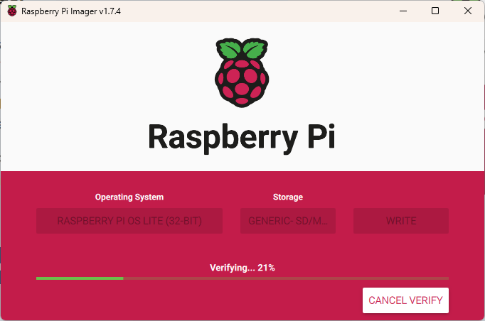
Click the “CHOOSE STORA…” button to select your microSD card, then click the “WRITE” button. The OS will be installed to your card. Once the verification completes and is successful, eject the card and put it in the Raspberry Pi. Start the Raspberry Pi by pressing the power button on the LiPo Amigo Pro.
SSH into the Raspberry Pi
If you don’t have PuTTY or other terminal software installed, now is a good time to head over to https://www.putty.org/ to download and install PuTTY. Once installed, open PuTTY and connect to your Raspberry Pi using the hostname that you setup when installing the OS to the card. If you cannot open a session, you may need to connect to your wireless router to determine the IP Address assigned to the Raspberry Pi and use that to connect.
Using one of the available text editors, edit /boot/config.txt. I’m using Nano, so I issued the following command. (Don’t forget sudo or you will be opening a read-only version.
sudo nano /boot/config.txt
Add the following lines at the end of /boot/config.txt, then reboot the Raspberry Pi.
# Disable Bluetooth - switch UART
dtoverlay=pi3-disable-bt

enable_uart=1
Install Hermes terminal emulator on your Psion device. On the PiRS232 board, the switches should be in the TX:TX/RX:RX and RTS:CTS/CTS:RTS positions.
NOTE TO SELF: It has been a long time since I needed to take a screenshot on a Psion device. On the 5mx, press CTRL+FN+SHIFT+S. On Windows, use an application such as XnView to open the screenshot and convert to another format.
Once the Raspberry Pi reboots and Hermes is installed on the Psion, open Hermes. On the menu, select Connection> Connection… (or Ctrl+K). Select the following options, then click the “OK” button.
Comms: Serial port 0
Baud rate: 115200
Settings: 8 data; 1 stop; No parity
Handshaking: Hardware (RTS/CTS)
If you get a dialog stating “Opening serial port Access denied”, you will need to disable the remote link.
On the System screen, open the menu and select Tools > Remote link… (or Ctrl+L).
Change the Remote Link setting to “Off”.
When connected to the Raspberry Pi, it may be necessary to press the Enter key once or twice to receive the login prompt from the Raspberry Pi.
It is now possible to work directly from the Psion or using PuTTY.
Setting up Flow Control
These commands may be entered from the Psion or PuTTY. I’m using PuTTY because it is easier to copy and paste. Issue the following commands.
sudo apt-get update

sudo apt install build-essential git
git clone https://github.com/mholling/rpirtscts
cd rpirtscts
make
sudo ./rpirtscts on

wget https://github.com/HiassofT/AtariSIO/blob/master/contrib/rpi/uart-ctsrts.dtbo?raw=true -O uart-ctsrts.dtbo
sudo mv uart-ctsrts.dtbo /boot/overlays/

sudo nano /boot/config.txt
Add the following at the end of /boot/config.txt, then save the file and exit the Nano editor. The first, second, and the last lines should already exist from the last step, when we edited the /boot/config.txt file. We are adding the third line here.
Once the file has been saved and we are back at the command line, edit ~/.bashrc file by issuing the following command. NOTE: Kian edits ~/.bash_rc but that file did not exist and creating it and adding the line did nothing. I needed to edit ~/.bashrc instead. Editing ~/.bashrc enabled flowcontrol for my setup.
nano ~/.bashrc
Add the following line at the end of the file.
stty -F /dev/ttyAMA0 crtscts
When using PuTTY or other SSH application, you may notice that there is an error when you login that states, “stty: /dev/ttyAMA0: Permission denied”. This is not an issue and does not show on the Psion 5mx serial connection. It may be possible to edit ~/.bashrc to only execute the command that we added if there are connected over a serial connection. That will take some further investigation but is a low priority. If you know how to detect the connection type and how to change the ~/.bashrc file, please leave a comment.
Optional – Install CMatrix
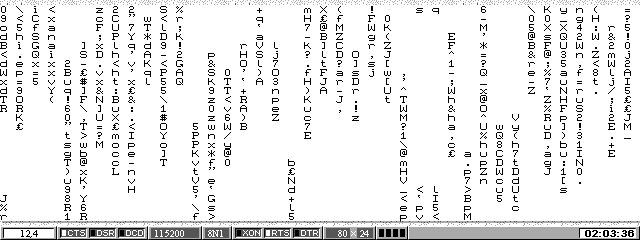
CMatrix is not necessary to install but it is a good test for the serial connection and it just looks cool. From either PuTTY or the Psion, issue the following commands to install and run CMatrix.
sudo apt-get install cmatrix

cmatrix
CMatrix runs slow on the Psion 5mx with a serial connection but it works. To exit, press Ctrl+C.
Setting Up Point-to-Point Protocol (PPP)
If you have not already, please read Kian’s PPP setup and understand the security concerns and understand that the serial terminal will no longer be available after this step.
Run the following commands from PuTTY.
sudo apt install ppp

sudo nano /etc/rc.local
Add the following two lines to /etc/rc.local before “exit 0”, save the file, and exit the editor.
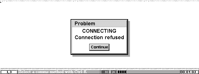
I ran into an issue when attempting to connect to the internet. Hermes would not connect.
The issue turned out to be quite obvious once it dawned on me that telnet server does not exist on the Raspberry Pi. There is a good reason that it is not installed. Telnet is a security concern as it is unencrypted. Keep this in mind if you install telnet on your Raspberry Pi. To install telnet, run the following command.
sudo apt-get install telnetd
Once telnet server was installed, things worked as Kian has in his blog post.
Well, I hit another snag. It appears that I cannot connect to the internet through the Raspberry Pi. DNS was not resolving domain names, so I attempted to browse by IP Address but that did not work either.
A more permanent solution is to edit /etc/sysctrl.conf and /etc/rc.local. First edit /etc/sysctrl.conf by using the following command.
sudo nano /etc/sysctl.conf
Find the commented line “#net.ipv4.ip_forward=1” and uncomment it, save the file, and exit the editor.
# Uncomment the next line to enable packet forwarding for IPv4
net.ipv4.ip_forward=1
Next edit /etc/sysctrl.conf by using the following command.
sudo nano /etc/rc.local
Add the following line before “exit 0”, then save the file and close the editor.
iptables -t nat -A POSTROUTING -o wlan0 -j MASQUERADE
Reboot the Raspberry Pi. Once the Raspberry Pi reboots, attempt to browse the internet on the Psion.
Closing Up the Case
Now that the software is in working order, we can put everything in the case and close it up. First start by carefully placing the stack in the case. It is a bit of a challenge to get the standoff into case without breaking the case but it will go, you just need to be careful.
The standoffs don’t protrude through the bottom, so no worries that it will scratch the table. 😉
The DB9 screw did not hit the Pimoroni LiPo Amigo Pro, so I was able to put it back on, then I installed the Pimoroni LiPo Amigo Pro on its self by attaching it with one M2.5 5mm screw.
Installed the battery and taped down the wires so they were not in the way of the switch.
Now close it up by attaching the lid with the M3 screws. I used a bit of tape to keep the button in place while I put it all together.
It seems that my Psion collection has been taking most of my attention. I’ve been testing some CF, SD, and microSD cards in my Psion 5mx and Ericsson MC 218. I also came across Kian Ryan’s Sidecar for Psion devices to connect them to the internet.
I had a similar idea to Kian’s Sidecar project but instead of an RS232 connection, I was thinking of an IrDA connection. I’ve purchased the items to build Kian’s Sidecar and plan to make one once all the parts arrive. Once I get that working, I plan to design and build an IrDA version. If all goes well, I plan to sharing it with the community. I think that an IrDA version would be much nicer as it would not require carrying a serial cable.
I’ve also purchased some 2GB CF, SD, and microSD cards as well as adapters so I could test them in my Psion 5mx and Ericsson MC 218. At first they seemed to not work, then I came across a video from Handheld Computing titled, “Formatting and Partitioning Compact Flash Cards for Psion“. The video is a bit too quick in key parts but slowing the video down and pausing it in key areas led me to a solution to get the cards working on the Psion devices.
Steps to format CF, SD, or microSD cards to work in a Psion PDA. Below are a few key takeaways of what needs to be done.
No partitions over 2GB
Format using FAT 16, not FAT32
Max cluster size is 32 KB
There must be some unallocated space on the disk. 1 MB is enough.
Below are some steps using Microsoft Windows and Mini Tools Partition Wizard software.
If you have not downloaded and installed Mini Tools Partition Wizard or similar tool, install the software first. Mini Tools Partition Wizard is free and available at https://www.minitool.com.
Launch the partitioning software, accept the Windows User Account Control prompt, then locate the flash card in the list of drives.
Right-click on the drive and select “Delete” from the context menu
Click the “Apply” button to make the changes
Right-click on the drive and select “Create” from the context menu or click “Create Partition” in the left side panel
Edit the following items
Make certain that the “Partition Align to” is set to MB
File System: FAT
Cluster Size 32 KB
Reduce the Partition Size by 1 MB so that Unallocated Space After is 1 MB
Optionally, set the Partition Label
Once the values have been changed, click the “OK” button
Click the “Apply” button to apply the changes
Close the software and insert the card into the Psion. If using a SD or microSD card, you will need to use a CF adapter.
The Psion should recognize the card.
If you see “Disk not present” or “Corrupt”, it is possible that the card will not be usable in the Psion. If you are using a SD or microSD card, it may be worth trying a different adapter. The good news is that every card I tested worked just fine after following the above process.
I did have an issue with a microSD to CF adapter but I was not surprised as it has a WiFi module in it. Most likely it was pulling more power than the Psion could deliver, which made it unusable. I had anticipated that but wanted to give it a try.
Below is a table showing the cards that I tried and a note if they worked or not. The cards names link to the Amazon product page.
There are many topics this week to cover, thus the reason for the non-descript title. Some of the things that have come up this week are Psion and Ericsson repairs, ChatGPT and DeepSource, and Agile2023.
Psion and Ericsson repairs
I was able to carryout another screen cable repair this week on the Ericsson MC 218. The MC 218 had the hooks in the back for the lid hinge so this repair resulted in a good as new repair. It did pose a challenge as the hinge is really not designed to be put in place while connected to the screen. I feared that I was going to break the plastic hooks so I worked to remove the pins holding the wire hinge from the screen. It was not easy and after I removed them, I saw that doing so caused a different challenge. The pins holding the wire hinges in place are actually spring metal wound up into a pin shape. This made them difficult to put back into place. The removal of the pins did make it much easier to get the wire hinges over the plastic hooks without breaking them, but I do not recommend doing that. If I carry out this repair again in the future, I plan to figure a better way to choregraph putting it all back together without breaking the hooks.
I feel that the terminology that I’m using to describe the hinge mechanism on the Psion 5 Series devices is not correct. If Martin Riddiford or anyone else in the know happens across this post, please add a comment below to let us know what the proper names for these are. Also a drawing with text pointing to them would be awesome as well.
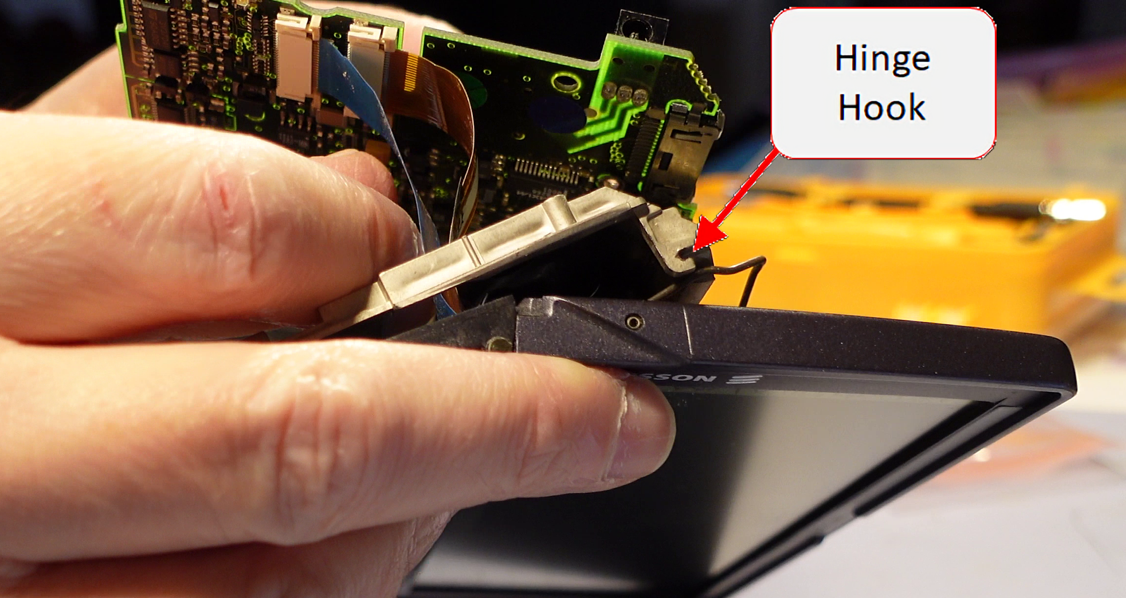
I captured a video of the repair and hope to find some time shortly to edit it and post it to YouTube. I will post an update with a link to the video once it is available. In the meantime, here are some screen grabs from some of the video to show the hinge assembly and the spring metal pins referenced above.
Screen with showing wire hinges and spring metal pins.Unit with showing one of the two hinge hooks.A view of the other hinge hook.Another view of the hinge hook.
Hinge Repair
The hinge repair that I carried out last week, did not last long, which was not too much of a surprise. The metal pins bent and allowed the hinges to pop out from under the cover. I straightened the pins and used my 3Doodler, to add some PLA around the pins to give them a bit more strength so they hopefully will last a bit longer. The repair looked ugly but no one will see how bad I am at using the 3Doodler.
The opening and closing of the unit is very tight after the repair, which makes me a bit uncomfortable so I will take it easy when opening and closing the unit.
Hinge repair before and afterHinge repair before and after for the other side
ChatGPT and DeepSource
It looks like things may be starting to really take off in the Artificial Intelligence (AI) field. We are starting to see more and more application of AI in some of the products that we use. I had been following the latest news regarding ChatGPT and found it interesting that it was able to pass a law exam at two different universities. While it would not be at the head of the class, it is good enough to get a passing grade. This presents a lot of challenges for professors at universities.
I had not given it much thought until I saw a video, 10X Your Code with ChatGPT: How to Use it Effectively, by Dave Plummer showing how ChatGPT could be used by software developers and others. He showed how he was able to interact with ChatGPT to develop a small software application and how we all need to start to understanding how to use the tool in our workflows.
I have seen that Visual Studio is now prompting me with code completion, based on my previous actions and where I’m at in the code. It is kind of freaky seeing the IDE basically writing code for you. There were times that it seemed to get in the way but most of the time, it was a real time saver. I’m sure it will get even better in the near future.
We may be at at point in time when AI will really start to have an impact in how we work and in our daily lives. Let’s just say that it has my attention now.
DeepSource
As I was trying ChatGPT, one very good use case popped out, and that is to do code reviews. Typically I am a lone developer and one of the biggest disadvantages of being a lone developer is your code is rarely code reviewed by anyone. ChatGPT did a fairly good job but the length of code it can code review is very limited.
Looking into ChatGPT led me to look into tools for Code Review. I found an article at GeekFlare, 6 Best Automated Code Review Tools for Developers. The article listed DeepSource as number 3. I looked into the other options and settled on DeepSource. It has great integration with GitHub so it scans code each time it is checked in. I was able to clean up my code fairly quickly.
I’ve made a recommendation to the DeepSource Team to incorporate AI for code reviews, particularly for us lone developers. We may be a few years away from being able to have a really good AI performing code reviews, but I think that is something we will see in the very near future.
Agile2023
I received some news this week that my submission for the Agile2023 conference was accepted. Now, I need to focus on polishing and practicing the workshop. This will be my first time presenting at a conference, so I’m nervous and excited for the opportunity. I hope it goes well and starts me down a path for the future.
I’ve had a busy week fixing items that have broken or that I bought on eBay that were for parts only.
Air Fryer
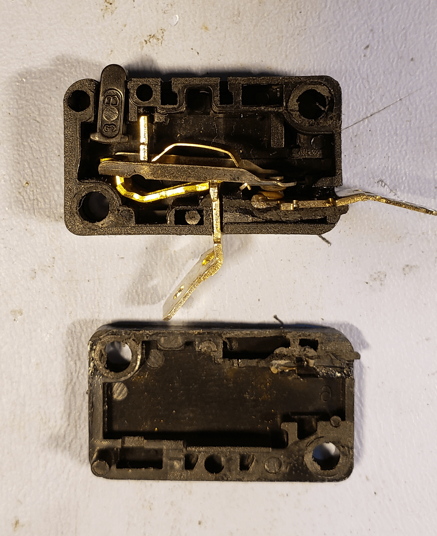
The Air Fryer, that we purchased on Amazon in March 2021 broke after 1 year and 10 months of service. At first, it would not shut off when the handle was lifted but after bumping it once, it shut off an would not come back on. I tool it apart to see if it could be repaired and found that the microswitch that turns the unit on when the handle is moved, failed. I was able to order a new one and replace it. It is working once again. Hopefully it will last a bit longer this time.
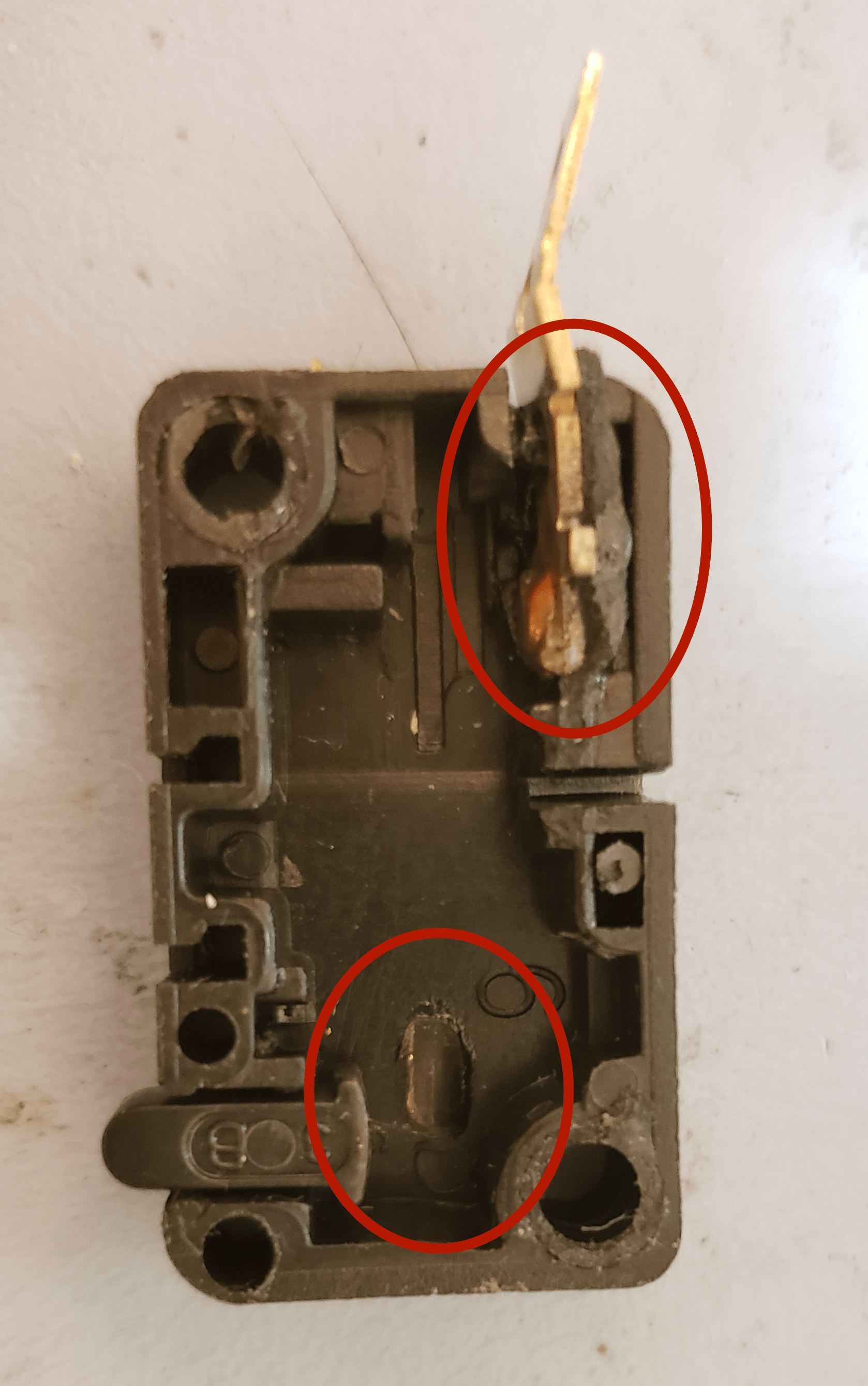
Curiosity got the best of me and I cracked open the microswitch to see how it failed as the failure seemed odd. The plunger on the switch was loose and I was not expecting that from a failed microswitch. Once it was cracked open, I could see that apparently the contacts had welded shut and created a lot of heat, which melted the plastic. It was a combination of these things that made it fail the way it did.
Switch cut open showing how it failed.Switch cut open with most internals removed to show melted plastic.
If interested, here are the links to the Amazon product pages for the Air Fryer and the replacement switch.
I have an obsession for the old Psion PDAs and have an unhealthy collection of them. Lately I made a purchase of a lot with four defective Psion devices. The idea is if I can’t fix them, I should at least be able to repurpose the keyboard for some future project. (I’m also doing the same with the HP 95lx devices.)
Diamond Mako Revos
The lot of four Psion devices now has three functional units. I first worked on the Diamond Mako Revo devices. One unit was disassembled and the other one worked but needed to be plugged in as it no longer held a charge. I took to Amazon and purchased 4 Ni-MH AAA batteries with solder tabs. I was able to get both units working by replacing the batteries. I did have to use some hot glue to reenforce the lower pins holding the back cover in place. They seem to be brittle on both sides. A bit of carefully placed hot glue seemed to be enough to hold them in place.
The circle shows where the lower pin on the spring was cracked on the both Revos.
I had another issue with the devices. At first, they did not seem to want to stay powered on even though they were plugged into the power supply. I could not figure out why the units would not stay on, so I started looking at them very carefully. I had discovered that the negative terminal in the battery connector had bent over and was touching the temperature sensor pin. It was not easy but I was able to straighten the pin and pulled the wire from the plug to make certain that it was fine. I carefully plugged the battery back in and they worked as expected.
What made this easier to figure out what was going on was by using the test points on the board. I was able to tell that the negative voltage was not where it should be, which led me to look closely at the plug and jack for the battery connection.
The test points on the battery PCB showing where the battery voltage should be present when all is connected as it should be.
The Psion 5MX and the Erickson MC 218, both had broken display cables, which is a common failure for Psion 5MX devices. I was able to order some replacement cables from Psionex. Nick and Rudy at Psionex were real helpful when I contacted them to verify that the Erikson MC 218 used the same screen cables as the Psion 5MX. I was surprised at how quickly they responded. It was late on this side of the pond so I did not expect a response from anyone until the next day but within an hour or two from submitting the contact request form, they got back to me.
The Psion 5MX that I received from eBay was in rough shape but I powered it on and I found that it had an issue with the screen cable, just like the Ericson. Since it was in the worst shape, I decided to disassemble it first as a practice run.
All went well and I was able to take the unit apart and replace the cable. I did find that it was easier to cut the ribbon cable to separate the touch screen controller before attempting to unsolder the cable. I thought using my hot air soldering station would be quicker but right away, I saw it melted some of the tape and other things around the screen so I just used my soldering iron. It was not too bad to remove and solder the new cable in place.
Fortunately, I was so concerned that things did not go well that I connected everything on the bench before reassembling the unit. I found that even though I measured the resistance on the touch screen connection, something was not right. The screen was spot on though so I was happy about that. It was a bit tricky but I was able to reflow the solder on the touch sensor connections and when I tested again, everything was in working order.
I started reassembling the unit and thought that the hinges seemed to be off, but I could not determine what the problem was. When it was finally all reassembled, the wire hinges popped out from under the rear cover. I then went back to Dave Savery’s page and finally saw that there were supposed to be hooks to keep them in place. I had to think of something so I used some leads from resistors that I had saved and melted them into the plastic and formed some hooks to keep the hinges in place. Hopefully that is enough to keep them in place as long as I use it. We shall see but it looks fine for now.
One of the hooks that were missing on my unit.On the left is the defective Ericsson MC 218 and on the right is the repaired Psion 5MX.
The repaired Psion 5MX is now my spare unit as the hinge repair job is not perfect. There is now some play in the unit so it does not close tightly. The keyboard and screen flop around by about 1/8″ (3 mm).
Below is a link to the Cables on Psionex. I’m not certain how much longer they will be in stock, but I will be reaching out to them again if I’m in need of any more. I’m including the link to the Series 5 cable as well.
Andrew Menadue has a project which recreates the Psion Organiser II with the Raspberry Pi Pico and ESP32-WROOM-32. He has several videos on YouTube and some GitHub repositories. Andrew was nice enough to send me a set of boards, which I’m in the process of building.
Bill of Materials
The bill of materials is an Excel document located on GitHub.


You must be logged in to post a comment.