
I found a project that Kian Ryan put together to get his Psion 5mx on the internet. It will not run YouTube or provide the content that we are used to today but it can provide a 1990’s internet experience.
Kian wrote up his build in a few of his blog posts. Below is a list of his blog posts. Please check them out for more details.
- The Sidecar for Psion – A PPP Modem and Linux Terminal for RS232 Devices
- RS232 and Null Modem Hat for the Pi Zero
- Connecting a Psion 5mx to a Raspberry Pi with Serial
When I saw the video of Kian on Tom’s hardware, I immediately went to his blog to see how he put it together. I had been thinking of doing something similar and seeing what Kian had would save me a great deal of time. I do plan to make another version of his project using IrDA. I already have the parts that I believe I will need to make it happen. I want to get the RS232 version working first. I sourced and ordered the parts that I did not have on hand. A little over 2 weeks later, the last parts arrived so I could get started.
The first thing that I worked on was building the PiRS232 board. I had not paid attention to Kian’s instruction to use tall headers. I did not have tall headers on hand so I had to order some. A couple days later, the proper headers arrived so I could complete the build.
Parts List & Sources
- Raspberry Pi Zero W
- Quantity: 1
- Source: Good Luck right now. Check https://rpilocator.com/ to see if you can find them in stock.
- Pimoroni LiPo Amigo Pro
- Quantity: 1
- Source: Pimoroni
- Pimoroni LiPo SHIM for Raspberry Pi
- Quantity: 1
- Source: Pimoroni
- 2200mah LiPo Battery with JST connector
- Quantity: 1
- Source: Pimoroni
- Double ended JST connector
- Quantity: 1
- Source: Pimoroni
- 2×20 Long Male Header (
19mm16mm)- Quantity: 1
- Source: Digi-Key S2072E-18-ND
- M2.5 10mm+6mm Nylon stand-offs (F-M), screws and nuts
- Quantity: 3
- Source: Amazon B07JYSFMRY (Kit)
- M2.5 5mm screws
- Quantity: 4
- Source: Amazon B07HC3LQYS
- M3 brass inserts
- Quantity: 2
- Source: Amazon B07ST8X41M
- M3 round head hex nut 8mm bolts
- Quantity: 2
- Source: Amazon B07FCN64HV
- Case
- Quantity: 1
- Source: Print the 4 STL files in the Case folder in Kian’s GitHub Repository. Optionally, you may printed on Printables
- Assembled PiRS232 board (See parts list below)

Parts for the PiRS232 Board
- PCB for PiRS232 board
- Quantity: 1
- Source: Use the PiRS232.kicad_pcb in Kian’s GitHub Repository and have it made at PCBWay, OSHPark, or other PCB manufacturer. Another way is to go to the OSHPark project that I created and order it from there.
- SP3232E
- Quantity: 1
- Source: eBay
- Search: https://www.ebay.com/sch/i.html?_nkw=SP3232E
- Vendor that I purchased from: longsheng-electronic. They were $6.88 + $390 US S&H for a total of $10.78 for 5 pieces.
- 0.1uF Capacitors
- Quantity: 5
- Source: Digi-Key 399-4264-ND
- Switch Slide DPDT
- Quantity: 2
- Source: Digi-Key 401-2000-ND
- DB9 Male Right Angle
- Quantity: 1
- Source: Amazon B00C57Y7E6

3D Printing the Parts
I had printed the parts with ABS filament on an XYZprinting da Vinci 1.0 3D Printer. Below are the images from Simplify3D showing the orientation of the pieces.


PiRS232 Board Build
The first step was to solder the 0.1uF capacitors to the board.

Next was to install the SP3232E IC. Take note of pin 1 and orientate the IC correctly. Start by soldering 2 opposing corner pins. Make certain that the IC is mounted flush, then solder the remaining pins.


The switches were next. The same principle of soldering opposing corner pins, checking placement, then soldering remaining pins was done with the switches and then the DB9 connector.


Putting the Stack Together
Once the correct headers arrived, I could get to work putting everything together and move on to the software.

Soldering the long header to the Raspberry Pi Zero. The header that I have is 19mm but 16mm looks to be a better fit. After soldering the header, the excess needed to be trimmed with flush cutters. It is handy to use a breadboard to help keep the pins straight. It may be necessary to prop up the Raspberry Pi to keep everything straight. Again, start with opposite corner pins, check the alignment, adjust if necessary, then solder the remaining pins.

Place the LiPo Shim on the Raspberry Pi and solder in place. Make certain that it does not touch any components and remains parallel to the Raspberry Pi.


Install the 10mm+6mm standoffs with nuts.

I did not like how the pins from the switch were right on top of the power connection so I place a bit of electrical tape over the pins.

Secure the PiRS232 board to the standoffs and solder the header pins.

If your headers are long, then trim them flush with the board.


Secure the LiPo Amigo Pro to the 3D Printed Power Rest with two or three M2.5 5mm screws.

Checking the fit for the LiPo Amigo Pro, it looks like the screw for the DB9 connector is going to be in the way, so we will need to remove it. It also looks like the threaded bracket is in the way as well so that too needs to be removed.


The fit is better but it looks like we may still need to make an adjustment. We will see when it all goes into the case.

Everything is all wired up, now on to the software. It is tempting to install it in the case but we need to be certain that the software is configured and ready before stuffing it in the case as the card is not accessible once everything is installed.

Software Setup
Using the Raspberry Pi Imager, setup a headless installation. If you don’t have the Raspberry Pi Imager installed, head over to https://www.raspberrypi.com/software/ and download the Raspberry Pi imager. Once installed, launch it and click the “CHOOSE OS” button.

Click the “Raspberry Pi OS (other)” option

Click the “Raspberry Pi OS Lite (32-bit)” option.

Click the gear icon in the lower right corner.


Setup the following options.
- Set a hostname
- Enable SSH (Typically you will want to use password authentication.)
- Set username and password to something that you will remember.
- Configure wireless LAN with your network SSID and password. Make certain that your Wireless LAN country is poperly set as well.
- Set local settings so your time zone and keyboard are correct.
- Setup the persistent settings to your liking.
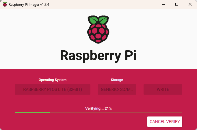
Click the “CHOOSE STORA…” button to select your microSD card, then click the “WRITE” button. The OS will be installed to your card. Once the verification completes and is successful, eject the card and put it in the Raspberry Pi. Start the Raspberry Pi by pressing the power button on the LiPo Amigo Pro.

SSH into the Raspberry Pi
If you don’t have PuTTY or other terminal software installed, now is a good time to head over to https://www.putty.org/ to download and install PuTTY. Once installed, open PuTTY and connect to your Raspberry Pi using the hostname that you setup when installing the OS to the card. If you cannot open a session, you may need to connect to your wireless router to determine the IP Address assigned to the Raspberry Pi and use that to connect.

Using one of the available text editors, edit /boot/config.txt. I’m using Nano, so I issued the following command. (Don’t forget sudo or you will be opening a read-only version.
sudo nano /boot/config.txt
Add the following lines at the end of /boot/config.txt, then reboot the Raspberry Pi.
# Disable Bluetooth - switch UART
dtoverlay=pi3-disable-bt

enable_uart=1

Install Hermes terminal emulator on your Psion device. On the PiRS232 board, the switches should be in the TX:TX/RX:RX and RTS:CTS/CTS:RTS positions.
NOTE TO SELF: It has been a long time since I needed to take a screenshot on a Psion device. On the 5mx, press CTRL+FN+SHIFT+S. On Windows, use an application such as XnView to open the screenshot and convert to another format.
Once the Raspberry Pi reboots and Hermes is installed on the Psion, open Hermes. On the menu, select Connection> Connection… (or Ctrl+K). Select the following options, then click the “OK” button.
- Comms: Serial port 0
- Baud rate: 115200
- Settings: 8 data; 1 stop; No parity
- Handshaking: Hardware (RTS/CTS)

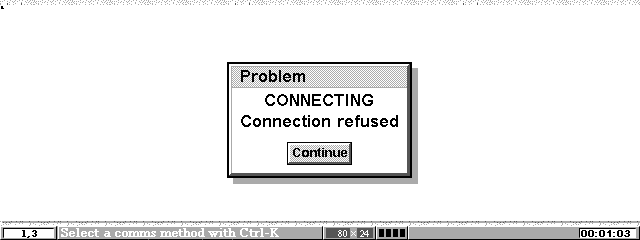
If you get a dialog stating “Opening serial port Access denied”, you will need to disable the remote link.

On the System screen, open the menu and select Tools > Remote link… (or Ctrl+L).

Change the Remote Link setting to “Off”.

When connected to the Raspberry Pi, it may be necessary to press the Enter key once or twice to receive the login prompt from the Raspberry Pi.

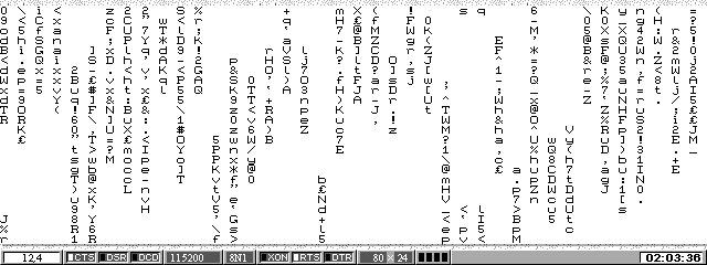
It is now possible to work directly from the Psion or using PuTTY.
Setting up Flow Control
These commands may be entered from the Psion or PuTTY. I’m using PuTTY because it is easier to copy and paste. Issue the following commands.
sudo apt-get update

sudo apt install build-essential git
git clone https://github.com/mholling/rpirtscts
cd rpirtscts
make
sudo ./rpirtscts on

wget https://github.com/HiassofT/AtariSIO/blob/master/contrib/rpi/uart-ctsrts.dtbo?raw=true -O uart-ctsrts.dtbo
sudo mv uart-ctsrts.dtbo /boot/overlays/

sudo nano /boot/config.txt
Add the following at the end of /boot/config.txt, then save the file and exit the Nano editor. The first, second, and the last lines should already exist from the last step, when we edited the /boot/config.txt file. We are adding the third line here.
# Disable Bluetooth - switch UART, enable CTS/RTS
dtoverlay=pi3-disable-bt
dtoverlay=uart-ctsrts
enable_uart=1
Once the file has been saved and we are back at the command line, edit ~/.bashrc file by issuing the following command.
NOTE: Kian edits ~/.bash_rc but that file did not exist and creating it and adding the line did nothing. I needed to edit ~/.bashrc instead. Editing ~/.bashrc enabled flowcontrol for my setup.
nano ~/.bashrc
Add the following line at the end of the file.
stty -F /dev/ttyAMA0 crtscts
When using PuTTY or other SSH application, you may notice that there is an error when you login that states, “stty: /dev/ttyAMA0: Permission denied”. This is not an issue and does not show on the Psion 5mx serial connection. It may be possible to edit ~/.bashrc to only execute the command that we added if there are connected over a serial connection. That will take some further investigation but is a low priority. If you know how to detect the connection type and how to change the ~/.bashrc file, please leave a comment.
Optional – Install CMatrix
CMatrix is not necessary to install but it is a good test for the serial connection and it just looks cool. From either PuTTY or the Psion, issue the following commands to install and run CMatrix.
sudo apt-get install cmatrix

cmatrix
CMatrix runs slow on the Psion 5mx with a serial connection but it works. To exit, press Ctrl+C.
Setting Up Point-to-Point Protocol (PPP)
If you have not already, please read Kian’s PPP setup and understand the security concerns and understand that the serial terminal will no longer be available after this step.
Run the following commands from PuTTY.
sudo apt install ppp

sudo nano /etc/rc.local
Add the following two lines to /etc/rc.local before “exit 0”, save the file, and exit the editor.
stty -F /dev/ttyAMA0 raw
sudo pppd /dev/ttyAMA0 115200 10.0.0.1:10.0.0.2 proxyarp local noauth nodetach dump crtscts passive persist maxfail 0 holdoff 1 &

Start raspi-config by issuing the following command.
sudo raspi-config
When Raspberry Pi Software Configuration Tool launches, go to Interface Options > Serial Port. Select “No” for shell and “Yes” for enabled.


Verify that the confirmation message states that the serial login shell is disabled and that the serial interface is enabled.

If the configuration is correct, select finish to exit and reboot the Raspberry Pi.

Setting Up the Psion
Jump over to Kian’s instructions.
I ran into an issue when attempting to connect to the internet. Hermes would not connect.
The issue turned out to be quite obvious once it dawned on me that telnet server does not exist on the Raspberry Pi. There is a good reason that it is not installed. Telnet is a security concern as it is unencrypted. Keep this in mind if you install telnet on your Raspberry Pi. To install telnet, run the following command.
sudo apt-get install telnetd
Once telnet server was installed, things worked as Kian has in his blog post.

Web Browsing
Opera is the best web browser for Psion devices, but it has only a 30-day demo. You need a license to use it past 30 days. It can be downloaded from https://get.geo.opera.com/pub/opera/. It looks like the latest version (19 April 2002) is at https://get.geo.opera.com/pub/opera/symbian/514/en/er5/.
Well, I hit another snag. It appears that I cannot connect to the internet through the Raspberry Pi. DNS was not resolving domain names, so I attempted to browse by IP Address but that did not work either.

To fix this issue, we need to do a bit more configuring on the Raspberry Pi. I found a couple of posts that helped me figure out how to fix the issue.
SOURCE: https://www.instructables.com/Connect-the-Raspberry-Pi-to-network-using-UART/ and https://www.ducea.com/2006/08/01/how-to-enable-ip-forwarding-in-linux/
The following two commands are a temporary way to get it all working.
sudo sysctl -w net.ipv4.ip_forward=1

sudo iptables -t nat -A POSTROUTING -o wlan0 -j MASQUERADE
A more permanent solution is to edit /etc/sysctrl.conf and /etc/rc.local. First edit /etc/sysctrl.conf by using the following command.
sudo nano /etc/sysctl.conf
Find the commented line “#net.ipv4.ip_forward=1” and uncomment it, save the file, and exit the editor.
# Uncomment the next line to enable packet forwarding for IPv4
net.ipv4.ip_forward=1
Next edit /etc/sysctrl.conf by using the following command.
sudo nano /etc/rc.local
Add the following line before “exit 0”, then save the file and close the editor.
iptables -t nat -A POSTROUTING -o wlan0 -j MASQUERADE
Reboot the Raspberry Pi. Once the Raspberry Pi reboots, attempt to browse the internet on the Psion.

Closing Up the Case
Now that the software is in working order, we can put everything in the case and close it up. First start by carefully placing the stack in the case. It is a bit of a challenge to get the standoff into case without breaking the case but it will go, you just need to be careful.

The standoffs don’t protrude through the bottom, so no worries that it will scratch the table. 😉

The DB9 screw did not hit the Pimoroni LiPo Amigo Pro, so I was able to put it back on, then I installed the Pimoroni LiPo Amigo Pro on its self by attaching it with one M2.5 5mm screw.

Installed the battery and taped down the wires so they were not in the way of the switch.

Now close it up by attaching the lid with the M3 screws. I used a bit of tape to keep the button in place while I put it all together.
