<- Part 1
Introduction
In the first part, I did some troubleshooting to fix an issue with the particular card readers that I have on hand. In part two, I will go over some code changes which allow the card reader to work without needing to add a capacitor to the data line and allowing the Arduino Nano to support two card readers.
I submitted an issue/comment to the magstripelib library in GitHub and was promptly received replies from Yoan Tournade and Carlos Rodrigues. Yoan suggested using INPUT_PULLUP on the interrupt pins may help. I modified the call to pinMode to use INPUT_PULLUP rather than INPUT but it made no difference. I suspect that there would be no difference as the card reader is pulling the pin up to the +5V rail so it is unnecessary to do in internal to the Arduino. It was worth a shot and I appreciated the suggestion.
Carlos commented that it is best to use an interrupt on the data pin as it reduces the amount of time spent in the clock interrupt handler. This is true but the I decided to rewrite the code to read the data pin inside the clock interrupt to solve two problems for my particular instance.
- Eliminate the need for the capacitor on the data line
- Allow an Uno or Nano to be able to read two card readers
I had planned to fork Carlos’s original code and make some changes to have him pull back in if he felt they added to the magstripelib but felt that the changes that I wanted to make serve a different goal from Carlos’s code. The changes that I made are for a very small audience of users if any at all so I chose to simply include modified header and class files into the Arduino project.
On to the Code
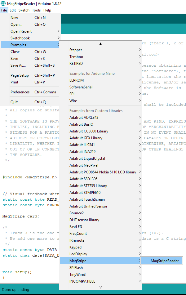
The following code is available on GitHub at https://github.com/richteel/MagCardReader.
Allowing the Arduino Nano to read two card readers was the real motivation for making the changes to the code. It did present a challenge that I had not anticipated. I had to figure out how to use the same interrupt code to read from a different data pin depending on this pin which fired the interrupt.
I wanted to be able to support 2 card readers on one Arduino Nano as the card readers that I have can be setup to read track 1 or track 2. The cover holding the reader head may be removed. The cover contains two sets of notches which allow the head to be in one of two positions. Since I have two readers, I configured one for track 1 and the other for track 2.
Below is a list of some of the code changes made from the magstripelib.
- Change class name from MagStripe to MagCardRead
- Added volatile variable to hold the current data pin number
- Modified the constructor to allow the assigning of the card detect, strobe (aka clock), and data pins for the reader
- Removed the data interrupt handler
- Read the data pin in the strobe interrupt handler
MagCardRead.h
/*
   MagCardRead - Read data from a magnetic stripe card.

   Copyright (c) 2020 Richard Teel <richteel@teelsys.com>

   Permission is hereby granted, free of charge, to any person obtaining a copy
   of this software and associated documentation files (the "Software"), to deal
   in the Software without restriction, including without limitation the rights
   to use, copy, modify, merge, publish, distribute, sublicense, and/or sell
   copies of the Software, and to permit persons to whom the Software is
   furnished to do so, subject to the following conditions:

   The above copyright notice and this permission notice shall be included in
   all copies or substantial portions of the Software.

   THE SOFTWARE IS PROVIDED "AS IS", WITHOUT WARRANTY OF ANY KIND, EXPRESS OR
   IMPLIED, INCLUDING BUT NOT LIMITED TO THE WARRANTIES OF MERCHANTABILITY,
   FITNESS FOR A PARTICULAR PURPOSE AND NONINFRINGEMENT. IN NO EVENT SHALL THE
   AUTHORS OR COPYRIGHT HOLDERS BE LIABLE FOR ANY CLAIM, DAMAGES OR OTHER
   LIABILITY, WHETHER IN AN ACTION OF CONTRACT, TORT OR OTHERWISE, ARISING FROM,
   OUT OF OR IN CONNECTION WITH THE SOFTWARE OR THE USE OR OTHER DEALINGS IN
   THE SOFTWARE.


   Modified from Carlos Rodrigues <cefrodrigues@gmail.com> original MagStripe library
   Based on this: http://cal.freeshell.org/2009/11/magnetic-stripe-reader/
     ...and this: http://www.abacus21.com/Magnetic-Strip-Encoding-1586.html
*/

#ifndef MAGCARDREAD_H
#define MAGCARDREAD_H

#include

// Default pins used by init
// The data and strobe pins depend on the board model...
#if defined(__AVR_ATmega32U4__)
// Arduino Leonardo and Arduino Micro:
#  define MAGSTRIPE_RDT 3  /* data pin (yellow) */
#  define MAGSTRIPE_RCL 2  /* strobe pin (orange) */
#else
// Arduino Uno and Arduino Mega:
#  define MAGSTRIPE_RDT 2  /* data pin (yellow) */
#  define MAGSTRIPE_RCL 3  /* strobe pin (orange) */
#endif

#  define MAGSTRIPE_CLS 4  /* card present pin (green) */

// Cards can be read in one of these possible ways...
enum ReadDirection { READ_UNKNOWN, READ_FORWARD, READ_BACKWARD };

class MagCardRead {
  public:
    MagCardRead(uint8_t cardDetectPin = MAGSTRIPE_CLS, uint8_t strobePin = MAGSTRIPE_RCL, uint8_t dataPin = MAGSTRIPE_RDT);

    // Initialize the library (attach interrupts)...
    void begin(uint8_t track);

    // Deinitialize the library (detach interrupts)...
    void stop();

    // Check if there is a card present for reading...
    bool available();

    // Read the data from the card as ASCII...
    short read(char *data, uint8_t size);

    // The direction of the last card read...
    enum ReadDirection read_direction();

  private:
    uint8_t _cardDetect_pin;
    uint8_t _strobe_pin;
    uint8_t _data_pin;

    uint8_t _track;
    enum ReadDirection direction;

    void reverse_bits();
    bool verify_parity(uint8_t c);
    bool verify_lrc(short start, short length);
    short find_sentinel(uint8_t pattern);
    short decode_bits(char *data, uint8_t size);
};


#endif  /* MAGCARDREAD_H */


/* vim: set expandtab ts=4 sw=4: */
MagCardRead.cpp
/*
   MagCardRead - Read data from a magnetic stripe card.

   Copyright (c) 2020 Richard Teel <richteel@teelsys.com>

   Permission is hereby granted, free of charge, to any person obtaining a copy
   of this software and associated documentation files (the "Software"), to deal
   in the Software without restriction, including without limitation the rights
   to use, copy, modify, merge, publish, distribute, sublicense, and/or sell
   copies of the Software, and to permit persons to whom the Software is
   furnished to do so, subject to the following conditions:

   The above copyright notice and this permission notice shall be included in
   all copies or substantial portions of the Software.

   THE SOFTWARE IS PROVIDED "AS IS", WITHOUT WARRANTY OF ANY KIND, EXPRESS OR
   IMPLIED, INCLUDING BUT NOT LIMITED TO THE WARRANTIES OF MERCHANTABILITY,
   FITNESS FOR A PARTICULAR PURPOSE AND NONINFRINGEMENT. IN NO EVENT SHALL THE
   AUTHORS OR COPYRIGHT HOLDERS BE LIABLE FOR ANY CLAIM, DAMAGES OR OTHER
   LIABILITY, WHETHER IN AN ACTION OF CONTRACT, TORT OR OTHERWISE, ARISING FROM,
   OUT OF OR IN CONNECTION WITH THE SOFTWARE OR THE USE OR OTHER DEALINGS IN
   THE SOFTWARE.


   Modified from Carlos Rodrigues <cefrodrigues@gmail.com> original MagStripe library
   Based on this: http://cal.freeshell.org/2009/11/magnetic-stripe-reader/
     ...and this: http://www.abacus21.com/Magnetic-Strip-Encoding-1586.html
*/

#include "MagCardRead.h"

#include

// Enough bits to read any of the three tracks...
#define BIT_BUFFER_LEN 800


// Variables used by the interrupt handlers...
static volatile bool next_bit = 0;                       // next bit to read
static volatile unsigned char bits[BIT_BUFFER_LEN / 8];  // buffer for bits being read
static volatile short num_bits = 0;                      // number of bits already read
static volatile uint8_t vdata_pin = 0;                   // data pin to be read by interrupt


// Manipulate the bit buffer...
static void bits_set(short index, bool bit);
static bool bits_get(short index);

// The interrupt handlers...
static void handle_strobe(void);

MagCardRead::MagCardRead(uint8_t cardDetectPin, uint8_t strobePin, uint8_t dataPin)
{
  _cardDetect_pin = cardDetectPin;
  _strobe_pin = strobePin;
  _data_pin = dataPin;

  direction = READ_UNKNOWN;
}

void MagCardRead::begin(uint8_t track)
{
  _track = track;

  pinMode(_cardDetect_pin, INPUT_PULLUP);
  pinMode(_strobe_pin, INPUT_PULLUP);
  pinMode(_data_pin, INPUT_PULLUP);

  // Reading is more reliable when using interrupts...
  attachInterrupt(digitalPinToInterrupt(_strobe_pin), handle_strobe, FALLING);  // strobe pin
}


void MagCardRead::stop()
{
  detachInterrupt(digitalPinToInterrupt(_strobe_pin));
}


bool MagCardRead::available()
{
  vdata_pin = _data_pin;
  return digitalRead(_cardDetect_pin) == LOW;
}


short MagCardRead::read(char *data, unsigned char size)
{
  // Fail if no card present...
  if (!available()) {
    return -1;
  }

  // Empty the bit buffer...
  num_bits = 0;
  next_bit = 0;

  // Wait while the data is being read by the interrupt routines...
  while (available()) {}

  // Decode the raw bits...
  short chars = decode_bits(data, size);
  direction = READ_FORWARD;

  // If the data looks bad, reverse and try again...
  if (chars < 0) {
    reverse_bits();
    chars = decode_bits(data, size);
    direction = READ_BACKWARD;
  }

  // The card could not be read successfully...
  if (chars < 0) {
    direction = READ_UNKNOWN;
  }

  return chars;
}


enum ReadDirection MagCardRead::read_direction()
{
  return direction;
}


void MagCardRead::reverse_bits()
{
  for (short i = 0; i < num_bits / 2; i++) {
    bool b = bits_get(i);

    bits_set(i, bits_get(num_bits - i - 1));
    bits_set(num_bits - i - 1, b);
  }
}


bool MagCardRead::verify_parity(unsigned char c)
{
  unsigned char parity = 0;

  for (unsigned char i = 0; i < 8; i++) { parity += (c >> i) & 1;
  }

  // The parity must be odd...
  return parity % 2 != 0;
}


bool MagCardRead::verify_lrc(short start, short length)
{
  unsigned char parity_bit = (_track == 1 ? 7 : 5);

  // Count the number of ones per column (ignoring parity bits)...
  for (short i = 0; i < (parity_bit - 1); i++) {
    short parity = 0;

    for (short j = i; j < length; j += parity_bit) {
      parity += bits_get(start + j);
    }

    // Even parity is what we want...
    if (parity % 2 != 0) {
      return false;
    }
  }

  return true;
}


short MagCardRead::find_sentinel(unsigned char pattern)
{
  unsigned char bit_accum = 0;
  unsigned char bit_length = (_track == 1 ? 7 : 5);

  for (short i = 0; i < num_bits; i++) { bit_accum >>= 1;                               // rotate the bits to the right...
    bit_accum |= bits_get(i) << (bit_length - 1);  // ...and add the current bit

    // Stop when the start sentinel pattern is found...
    if (bit_accum == pattern) {
      return i - (bit_length - 1);
    }
  }

  // No start sentinel was found...
  return -1;
}


short MagCardRead::decode_bits(char *data, unsigned char size) {
  short bit_count = 0;
  unsigned char chars = 0;
  unsigned char bit_accum = 0;
  unsigned char bit_length = (_track == 1 ? 7 : 5);

  short bit_start = find_sentinel(_track == 1 ? 0x45 : 0x0b);
  if (bit_start < 0) {  // error, start sentinel not found
    return -1;
  }

  for (short i = bit_start; i < num_bits; i++) { bit_accum >>= 1;                                 // rotate the bits to the right...
    bit_accum |= (bits_get(i) << (bit_length - 1)); // ...and add the current bit bit_count++; if (bit_count % bit_length == 0) { if (chars >= size) {  // error, the buffer is too small
        return -1;
      }

      // A null means we reached the end of the data...
      if (bit_accum == 0) {
        break;
      }

      // The parity must be odd...
      if (!verify_parity(bit_accum)) {
        return -1;
      }

      // Remove the parity bit...
      bit_accum &= ~(1 << (bit_length - 1));

      // Convert the character to ASCII...
      data[chars] = bit_accum + (_track == 1 ? 0x20 : 0x30);
      chars++;

      // Reset...
      bit_accum = 0;
    }
  }

  // Turn the data into a null-terminated string...
  data[chars] = '\0';

  if (data[chars - 2] != '?') {  // error, the end sentinel is not in the right place
    return -1;
  }

  // Verify the LRC (even parity across columns)...
  if (!verify_lrc(bit_start, chars * bit_length)) {
    return -1;
  }

  return chars;
}


static void bits_set(short index, bool bit)
{
  volatile unsigned char *b = &bits[index / 8];
  unsigned char m = 1 << (index % 8);

  *b = bit ? (*b | m) : (*b & ~m);
}


static bool bits_get(short index)
{
  return bits[index / 8] & (1 << (index % 8)); } static void handle_strobe() { // Avoid a crash in case there are too many bits (garbage)... if (num_bits >= BIT_BUFFER_LEN) {
    return;
  }

  next_bit = !digitalRead(vdata_pin);

  bits_set(num_bits, next_bit);
  num_bits++;
}


/* vim: set expandtab ts=4 sw=4: */
MagCardReader.ino
/*
   MagCardRead - Read data from a magnetic stripe card.

   Copyright (c) 2020 Richard Teel <richteel@teelsys.com>

   Permission is hereby granted, free of charge, to any person obtaining a copy
   of this software and associated documentation files (the "Software"), to deal
   in the Software without restriction, including without limitation the rights
   to use, copy, modify, merge, publish, distribute, sublicense, and/or sell
   copies of the Software, and to permit persons to whom the Software is
   furnished to do so, subject to the following conditions:

   The above copyright notice and this permission notice shall be included in
   all copies or substantial portions of the Software.

   THE SOFTWARE IS PROVIDED "AS IS", WITHOUT WARRANTY OF ANY KIND, EXPRESS OR
   IMPLIED, INCLUDING BUT NOT LIMITED TO THE WARRANTIES OF MERCHANTABILITY,
   FITNESS FOR A PARTICULAR PURPOSE AND NONINFRINGEMENT. IN NO EVENT SHALL THE
   AUTHORS OR COPYRIGHT HOLDERS BE LIABLE FOR ANY CLAIM, DAMAGES OR OTHER
   LIABILITY, WHETHER IN AN ACTION OF CONTRACT, TORT OR OTHERWISE, ARISING FROM,
   OUT OF OR IN CONNECTION WITH THE SOFTWARE OR THE USE OR OTHER DEALINGS IN
   THE SOFTWARE.


   Modified from Carlos Rodrigues <cefrodrigues@gmail.com> original MagStripe library
   Based on this: http://cal.freeshell.org/2009/11/magnetic-stripe-reader/
     ...and this: http://www.abacus21.com/Magnetic-Strip-Encoding-1586.html
*/

#include "MagCardRead.h"


#define pinCardDetect1 4
#define pinStrobe1 2
#define pinData1 5

#define pinCardDetect2 6
#define pinStrobe2 3
#define pinData2 7

// Visual feedback when the card is being read...
static const byte READ_LED = 8;  //13
static const byte ERROR_LED = 9; //12

//MagCardRead card;
//MagCardRead card(pinCardDetect);
MagCardRead card(pinCardDetect1, pinStrobe1, pinData1);
MagCardRead card2(pinCardDetect2, pinStrobe2, pinData2);

/*
   Track 3 is the one that can contain the most characters (107).
   We add one more to accomodate the final '\0', as the data is a C string...
*/
static const byte DATA_BUFFER_LEN = 108;
static char data[DATA_BUFFER_LEN];


void readCard(MagCardRead crd) {
  // Don't do anything if there isn't a card present...
  if (!crd.available()) {
    return;
  }

  // Show that a card is being read...
  digitalWrite(READ_LED, HIGH);
  Serial.println("-- Read Completed --");

  // Read the card into the buffer "data" (as a null-terminated string)...
  short chars = crd.read(data, DATA_BUFFER_LEN);

  // Show that the card has finished reading...
  digitalWrite(READ_LED, LOW);

  // If there was an error reading the card, blink the error LED...
  if (chars < 0) {
    digitalWrite(ERROR_LED, HIGH);
    delay(250);
    digitalWrite(ERROR_LED, LOW);
    Serial.println("Read Error...");
    Serial.println(chars);

    return;
  }

  Serial.println("Good Read...");
  Serial.print("Read Direction: ");
  //Serial.println(crd.read_direction());
  Serial.println(crd.read_direction() == 1 ? "Forward" : crd.read_direction() == 2 ? "Backward" : "Unknown");


  // Send the data to the computer...
  Serial.println(data);
}

void setup()
{
  pinMode(READ_LED, OUTPUT);
  pinMode(ERROR_LED, OUTPUT);

  // The card data will be sent over serial...
  Serial.begin(9600);

  // Initialize the library for reading track 2...
  card.begin(1);
  card2.begin(2);

  // Start with the feedback LEDs off...
  digitalWrite(READ_LED, LOW);
  digitalWrite(ERROR_LED, LOW);
}


void loop()
{
  readCard(card);
  readCard(card2);
}


/* EOF - MagCardRead.ino */
Conclusion
Most applications with card readers and Arduinos should make use of the magstripelib library by Carlos Rodrigues. If you have a project that uses one of the card readers mentioned in the original blog post then add a capacitor to the data line as mentioned in the original post. If for some reason, you cannot add a capacitor as mentioned or you need to read from two readers, then the code mentioned here may be a good solution.


You must be logged in to post a comment.