I purchased an LCD Shield for Arduino from eBay a few weeks ago. I wanted to do a review to help others to get the shield to run on their Arduino or other microprocessor.
Overall Impression
Works as stated and is a good value. I would recommend this shield if you are in the market for a low cost shield with buttons for user input. It is a great shield to get a project going.
Overview
I am not certain who designed the original shield but I assume that it is open-source as there are many similar shields on the market. It appears that most are built from the same schematic that I found on SainSmart’s website at https://www.sainsmart.com/collections/all-for-arduino/products/lcd-keypad-shield-for-arduino-duemilanove-uno-mega2560-mega1280.
The shield uses one analog pin to determine which of the five switches the user has pressed. A series of resistors creates a voltage divider which in turn creates specific voltages for each switched pressed. The pins in use on the board are as follows.
| Pin | Function | Pin | Function | |
|---|---|---|---|---|
| Reset | Reset Button | 10 | LCD – Backlight | |
| 5V | Power | 9 | LCD – Enable | |
| Ground | Ground | 8 | LCD – RS | |
| A0 | Buttons | 7 | LCD – D7 | |
| – SELECT | 6 | LCD – D6 | ||
| -LEFT | 5 | LCD – D5 | ||
| – UP – RIGHT – DOWN | 4 | LCD – D4 |
Code for Testing
The following code was found on SainSmart’s website. It was modified slightly to monitor the value of the A0 pin over the serial connection with the PC.
/*
  The circuit:
 * LCD RS pin to digital pin 8
 * LCD Enable pin to digital pin 9
 * LCD D4 pin to digital pin 4
 * LCD D5 pin to digital pin 5
 * LCD D6 pin to digital pin 6
 * LCD D7 pin to digital pin 7
 * LCD BL pin to digital pin 10
 * KEY pin to analogl pin 0
 */

#include <LiquidCrystal.h>

LiquidCrystal lcd(8, 13, 9, 4, 5, 6, 7);

char msgs[5][16] = {"Right Key OK ",
                    "Up Key OK    ",
                    "Down Key OK  ",
                    "Left Key OK  ",
                    "Select Key OK" };

int adc_key_val[5] ={50, 200, 400, 600, 800 };
int NUM_KEYS = 5;
int adc_key_in;
int key=-1;
int oldkey=-1;

void setup()
{
  // open the serial port at 9600 bps:
  Serial.begin(9600);

  lcd.clear();
  lcd.begin(16, 2);
  lcd.setCursor(0,0);
  lcd.print("ADC key testing");

  //analogReadResolution(12);
}

void loop()
{
  adc_key_in = analogRead(0);    // read the value from the sensor
  Serial.println(adc_key_in);
  key = get_key(adc_key_in);  // convert into key press

  if (key != oldkey)   // if keypress is detected
   {
    delay(50);  // wait for debounce time
    adc_key_in = analogRead(0);    // read the value from the sensor
    key = get_key(adc_key_in);    // convert into key press
    if (key != oldkey)
    {
      lcd.setCursor(0, 1);
      oldkey = key;
      if (key >=0){
           lcd.print(msgs[key]);
      }
    }
  }
 delay(100);
}

// Convert ADC value to key number
int get_key(unsigned int input)
{
    int k;

    for (k = 0; k < NUM_KEYS; k++)
    {
      if (input < adc_key_val[k]) { return k; } } if (k >= NUM_KEYS)k = -1;  // No valid key pressed
    return k;
}
The code does not perform any debouncing of the button presses so you may need to modify the code if it becomes a problem in your project. Another limitation is the shield and/or the code will not be able to determine if more than one switch has been pressed. I have not tested this, but my hypothesis is that the switch with the lowest resistance will be detected.
Issue with 3.3V Adruino Boards
First off, read the warning above as you may damage your Arduino if the microcontroller is running at 3.3V.
After receiving the shield from the seller, frentaly , on eBay, I pulled out my Arduino Due as it happened to be the first Arduino board that I grabbed. I ran the above code and had some strange results. Pressing the “SELECT” button did nothing. Pressing the “LEFT” button registered “SELECT” was pushed. Likewise, pressing “DOWN” registered that the “LEFT” button was pressed. The “UP” and “RIGHT” buttons worked as expected. I sent a message to frentaly as I believed there was a problem with the shield. I then observed that the resistors for the voltage divider were the correct values so I pulled out a Mega board and ran the same test sketch. I found that the LCD button shield worked as expected on the Mega board. I did some investigating and found that the microprocessor on the Due board is running at 3.3V therefore the highest voltage that may be read on any analog pin is 3.3V. I went a bit further to get a bit more information.
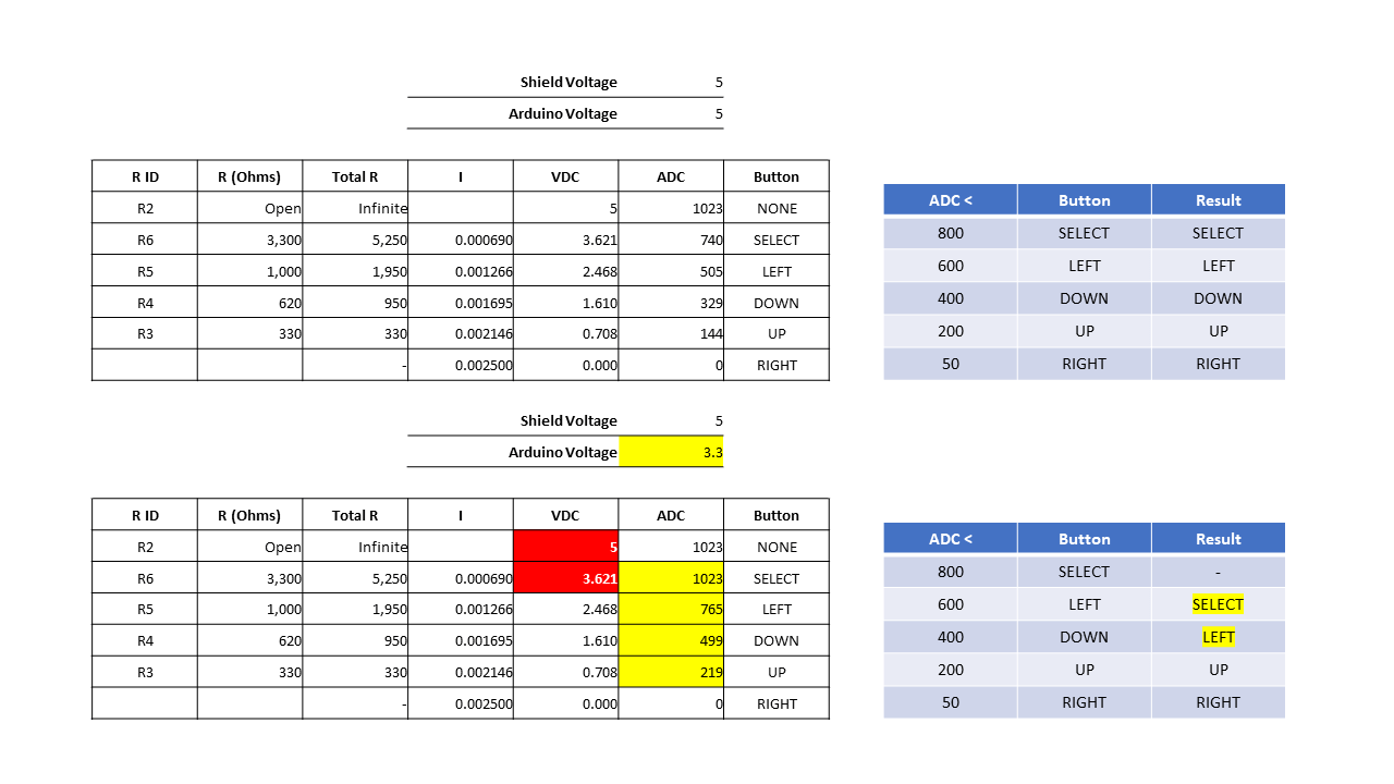
The table below provides some information regarding the ADC values reported on A0 with 5V and 3.3V microprocessor Arduino boards. In the table below there is not difference between no button pressed and the “SELECT” button being pressed.
|
Button |
R ID |
R (Ohms) |
Total R |
I |
VDC |
ADC 5V |
ADV 3.3V |
| NONE | R2 | Open | Infinite |
5 |
1023 |
1023 |
|
| SELECT | R6 | 3,300 | 5,250 |
0.000690 |
3.621 |
740 |
1023 |
| LEFT | R5 | 1,000 | 1,950 |
0.001266 |
2.468 |
505 |
765 |
| DOWN | R4 | 620 | 950 |
0.001695 |
1.610 |
329 |
499 |
| UP | R3 | 330 | 330 |
0.002146 |
0.708 |
144 |
219 |
| RIGHT | – |
0.002500 |
0.000 |
0 |
0 |
Here are some slides which provide some details on how the buttons work on the shield.
- No buttons pressed

- RIGHT button pressed

- UP button pressed

- DOWN button pressed

- LEFT button pressed

- SELECT button pressed

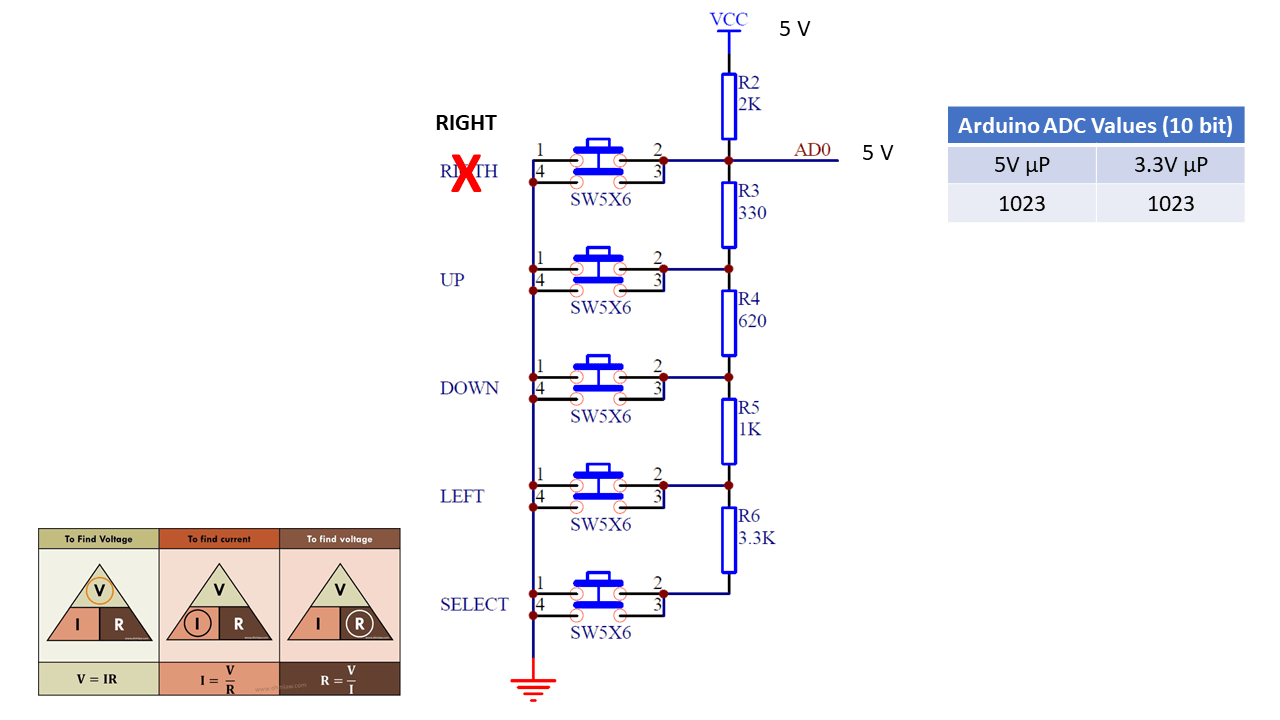
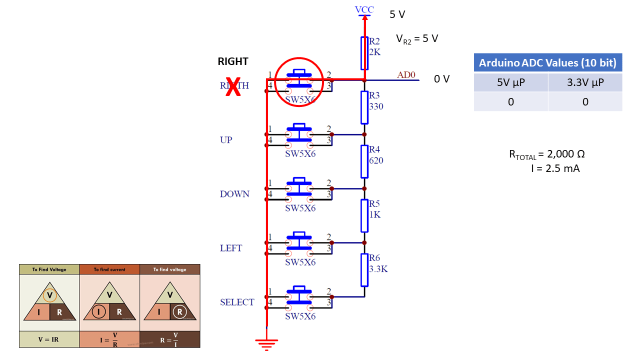

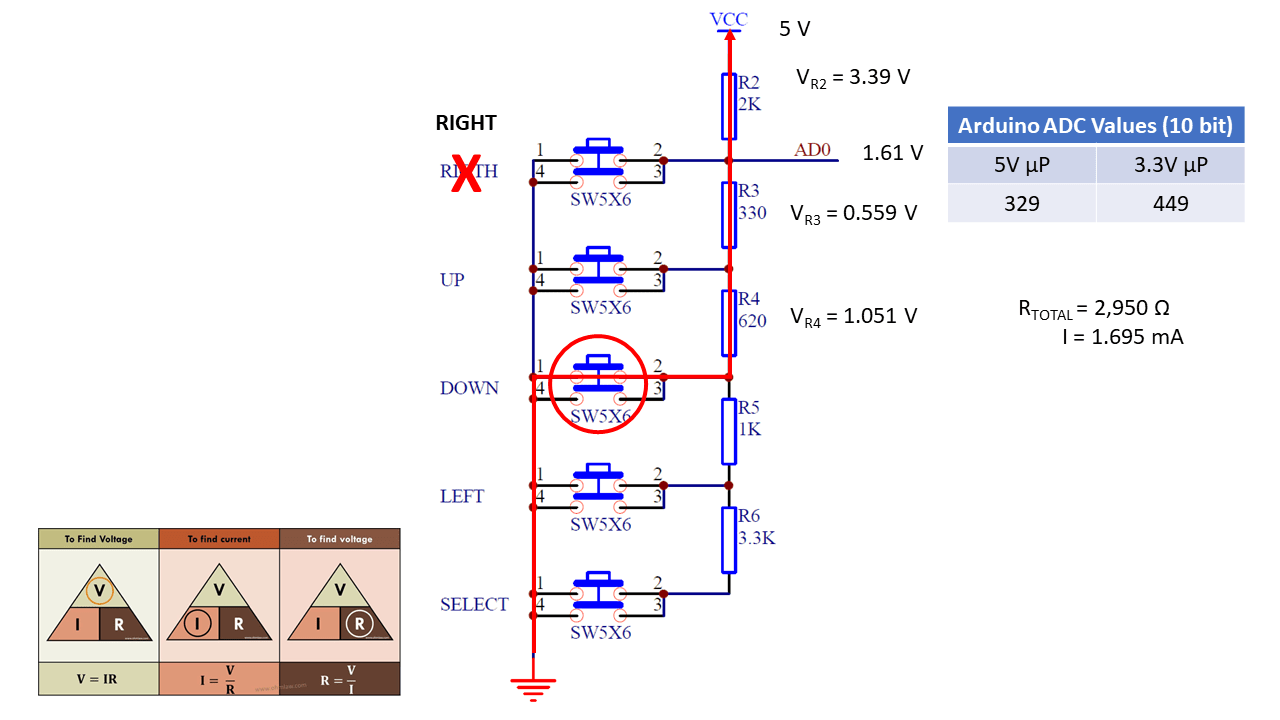


The schematic is from the SainSmart web page referenced above.
Below is the data presented above shown in a different format.