Introduction
I was cleaning up and found a project I abandoned about 20 years ago. I was attempting to read magnetic strip cards using the PC Parallel Port. I had done it previously with a different card reader but I had some trouble with these two particular units. I wanted to test them before I decided to get rid of them so I broke out an Arduino Nano and found the magstripelib library written by Carlos Rodrigues on GitHub. I could not get the readers to work with the code so I looked at the libraries but found no issue with them. I then found an issue with the hardware that was rather easy to solve.
The Magnetic Card Readers
I purchased the card readers from either All Electronics or Electronic Goldmine. (Both places are great for obtaining low cost surplus electronics.) The readers are made by Tokin and have a part number of MCS-131P-3. The PCB contains 1550-B014-00-1 and YEC YE-34V N markings.


I had recalled that there was an issue with the connector cable on the readers that I wanted to resolve. The red wire is connected to ground and the brown wire is connected to Vcc (+5V). This was verified by checking with an ohm meter. Additionally, there is a card sense connection but there is no wire. With a simple modification, we can switch the wires and add a new wire for the card sense connection. While we are at it, We will make the readers breadboard friendly by changing the connector to a 5 pin male header.
Modifying the Magnetic Card Reader
Step 1 – remove the PCB
Use a plastic tool or very carefully use a screwdriver to remove the hot glue holding the PCB in place and carefully slide the card out of the reader.


Once the card is free, you can see that the board layout is made to accommodate the correct connections but there was an effort made to switch the ground and Vcc wires.


Step 2 – Remove the strain relief zip-tie
Cut the zip-tie and remove.


Step 3 – Switch the red and brown wires
Unsolder the red and brown wires, switch them, and solder in place.


Step 4 – Add the card sense wire
Cut a length of stranded 26 AWG wire, strip the ends and solder to the card-sense connection.


Step 5 – Add the strain relief
Use a zip-tie to reapply the strain relief to the wire connector using the two holes in the PCB.


Step 6 – Reinstall the PCB
Carefully return the PCB to the plastic assembly by reinserting into the slot.

Step 7 – Remove the old connector
Cut off the old connector.

Step 8 – Prep the wires
Strip the ends of the wire and tin with solder.

Step 9 – Cut Heat-Shrink Tubing
Cut 5 pieces of 1/16″ heat-shrink to about 1/4″ in length and one or two pieces of 3/16″ heat-shrink tubing about 3/4″ in length.

Step 10 – Prepare male header pins
Cut a single-row male header to 5 positions.

Step 11 – Solder wires to header
Tin the short pins with solder. Slide the 3/16″ heat-shrink piece(s) over all of the wires together. Solder each wire to the tinned header pins by first sliding a 1/16″ heat-shrink tubing over each wire.

Step 12 – Shrink the heat-shrink tubing
You may want to use a breadboard to keep the pins aligned while heating the tubing as the plastic may become pliable and allow the pins to move. Heat the tubing to fix them in place.


Testing with the Arduino
Wire up the Arduino
The wiring will depend on the processor on the Arduino. If you are uncertain as to which processor your Arduino has, check out the Wikipedia article at https://en.wikipedia.org/wiki/List_of_Arduino_boards_and_compatible_systems.
The Arduino Nano uses the following wiring.
| Wire Color | Function | Arduino Pin |
|---|---|---|
| Brown | Ground | GND |
| Red | Vcc | 5V |
| Green | Card Detect | 4 |
| Orange | Strobe | 3 |
| Yellow | Data | 2 |
Load the example sketch
Connect the Arduino to the PC and start the Arduino IDE and add the magstripelib library by going to the menu Tools > Manage Libraries… Search for MagStrip and install the library by Carlos Rodrigues.

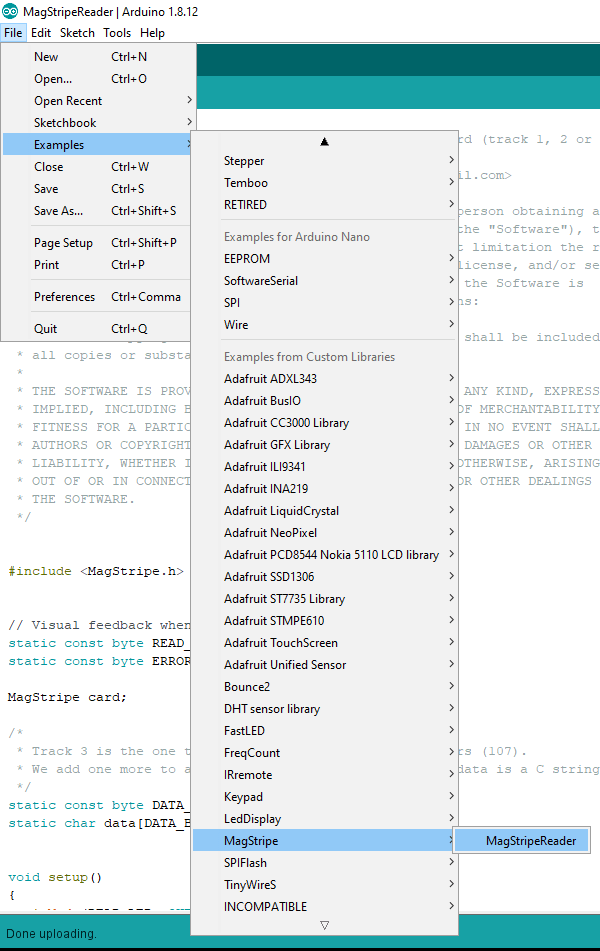
Load the MagStripe example by going to the menu File > Examples > MagStripe > MagStripeReader.
Make certain the correct board and port are selected then upload the code to the Arduino. Once the code is loaded, open the serial monitor and run a card through the reader to see if there is any data read. I did not receive any data so I added some lines of code to let me know that there was an issue. Below is the modified code. The modified code let me know that the card was detected and it attempted to read it but ran into an issue decoding the data.
/*
 * MagStripeReader - Read data from a magnetic stripe card (track 1, 2 or 3).
 *
 * Copyright (c) 2010 Carlos Rodrigues <cefrodrigues@gmail.com>
 *
 * Permission is hereby granted, free of charge, to any person obtaining a copy
 * of this software and associated documentation files (the "Software"), to deal
 * in the Software without restriction, including without limitation the rights
 * to use, copy, modify, merge, publish, distribute, sublicense, and/or sell
 * copies of the Software, and to permit persons to whom the Software is
 * furnished to do so, subject to the following conditions:
 *
 * The above copyright notice and this permission notice shall be included in
 * all copies or substantial portions of the Software.
 *
 * THE SOFTWARE IS PROVIDED "AS IS", WITHOUT WARRANTY OF ANY KIND, EXPRESS OR
 * IMPLIED, INCLUDING BUT NOT LIMITED TO THE WARRANTIES OF MERCHANTABILITY,
 * FITNESS FOR A PARTICULAR PURPOSE AND NONINFRINGEMENT. IN NO EVENT SHALL THE
 * AUTHORS OR COPYRIGHT HOLDERS BE LIABLE FOR ANY CLAIM, DAMAGES OR OTHER
 * LIABILITY, WHETHER IN AN ACTION OF CONTRACT, TORT OR OTHERWISE, ARISING FROM,
 * OUT OF OR IN CONNECTION WITH THE SOFTWARE OR THE USE OR OTHER DEALINGS IN
 * THE SOFTWARE.
 */


#include


// Visual feedback when the card is being read...
static const byte READ_LED = 13;
static const byte ERROR_LED = 12;

MagStripe card;

/*
 * Track 3 is the one that can contain the most characters (107).
 * We add one more to accomodate the final '\0', as the data is a C string...
 */
static const byte DATA_BUFFER_LEN = 108;
static char data[DATA_BUFFER_LEN];


void setup()
{
  pinMode(READ_LED, OUTPUT);
  pinMode(ERROR_LED, OUTPUT);

  // The card data will be sent over serial...
  Serial.begin(9600);

  // Initialize the library for reading track 2...
  card.begin(2);

  // Start with the feedback LEDs off...
  digitalWrite(READ_LED, LOW);
  digitalWrite(ERROR_LED, LOW);
}


void loop()
{
  // Don't do anything if there isn't a card present...
  if (!card.available()) {
    return;
  }

  // Show that a card is being read...
  digitalWrite(READ_LED, HIGH);

  // Read the card into the buffer "data" (as a null-terminated string)...
  short chars = card.read(data, DATA_BUFFER_LEN);

  // Show that the card has finished reading...
  digitalWrite(READ_LED, LOW);
  Serial.println("-- Read Completed --");

  // If there was an error reading the card, blink the error LED...
  if (chars < 0) {
    digitalWrite(ERROR_LED, HIGH);
    delay(250);
    digitalWrite(ERROR_LED, LOW);
    Serial.println("Read Error...");
    Serial.println(chars);

    return;
  }

  Serial.println("Good Read...");
  Serial.print("Read Direction: ");
  //Serial.println(card.read_direction());
  Serial.println(card.read_direction()==1 ? "Forward" : card.read_direction()==2 ? "Backward" : "Unknown");

  // Send the data to the computer...
  Serial.println(data);
}


/* EOF - MagStripeReader.ino */
The result was always a failed read no mater which card was read.
-- Read Completed --
Read Error...
-1
Troubleshooting
As mentioned in the introduction, I first focused on the code to see if I could find something that was amiss. I also attempted to switch the strobe and clock wires to see if I had identified them incorrectly. I then tried using an Arduino Uno to see if the Nano was a problem but I still could not successfully read a card. I then turned my attention to the hardware. The first thing that I did was to use my Tenma 72-8705 oscilloscope to look at the strobe and data lines. I noted that it looked like the data line had narrow spikes on some clock edges. I did not think much of it at the time.


Channel 1 is Strobe and Channel 2 is Data
I decided to break out the Saleae Logic Analyzer to capture the strobe and data lines and manually decode the data to see if the readers are working properly. I saw the same spikes on the data line which occurs with the rising clock edge.

Channel 0 is Strobe, Channel 1 is Data, and Channel 2 is Card Sense
Since the spikes occur on a rising clock edge, it really should not be an issue as the data is only valid on a falling clock edge. I exported the captured data into a CSV file and looked at it in Excel. I was able to decode the data and verified that the data was reading the card properly. To know that the data was read properly, it was necessary to read some of the information from Magtek.
- Magtek’s I/O Interface for TTL Magnetic Stripe Readers Technical Reference Manual
- Magtek’s Magnetic Stripe Card Standards
I took another look at the code and see that the data values are being flipped from the previous value. I was unable to determine what the width of the spikes are but I suspect that the spikes may flip the data value in the code but are not wide enough to raise the hardware interrupt on the Arduino when it returns to +5V. If this is the case then it is understandable why there are issues reading the cards. This could be fixed using hardware or software. I took the hardware approach by connecting a 0.01uF capacitor between the data line and Vcc. Once the capacitor was added to remove the spikes from the data line, the code was able to read the cards successfully.
Going Further
It may be possible to resolve the issue observed with this particular card reader by removing the interrupt from the data pin and reading the data value on the clock interrupt instead. This in turn would free up the hardware interrupt used for the data pin and allow any digital pin to be used for the data line. This may allow the reading of two track from readers which read multiple tracks or allow the use of more than one card reader.
One reply on “Magnetic Card Reader (TTL) with Arduino”
[…] <- Part 1 […]