Categories
Arduino CircuitPython Project Raspberry Pi Pico Software Development

September Update

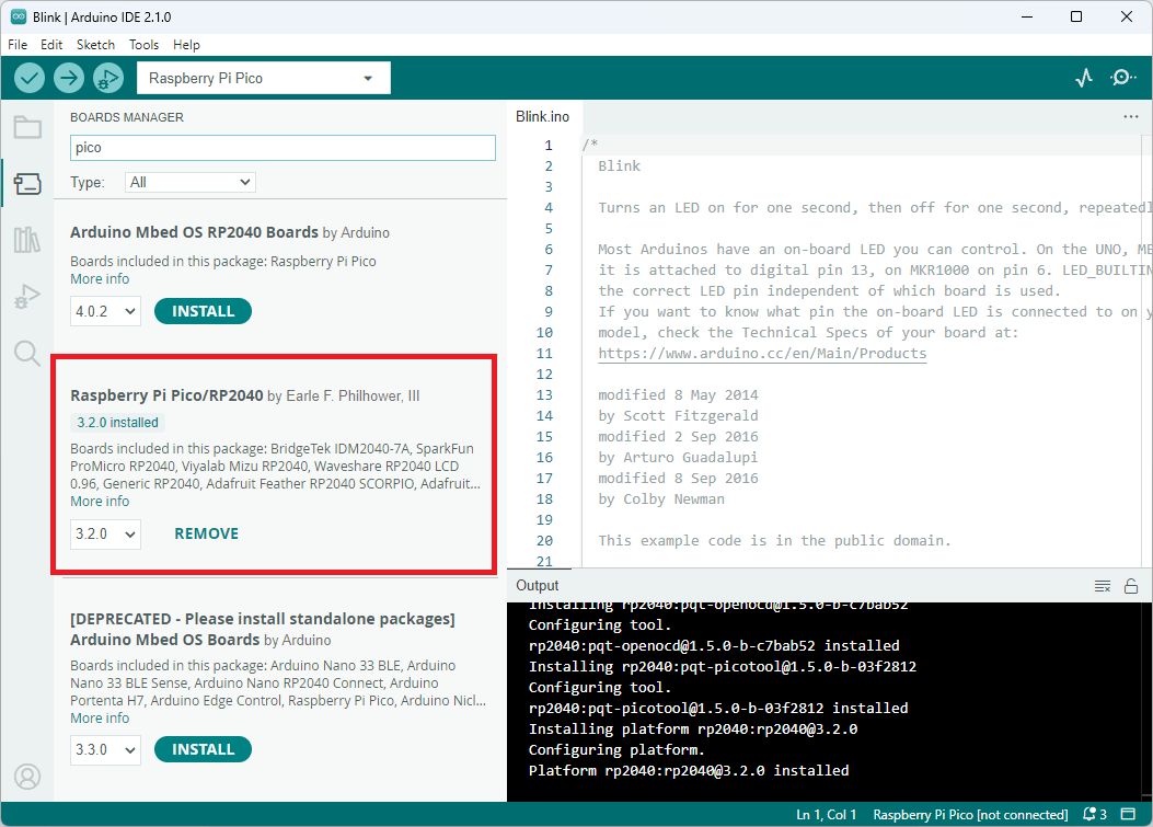
Another month has gone by and I am still working on the Speech Timer project. I was able to develop a solution with CircuitPython but was not happy with the end product. Perhaps it would be possible to get to a more stable version but even with all the RAM available on the Raspberry Pi Pico W, I would still run into issues with the heap becoming fragmented and not having enough free space to allocate additional space to server web pages reliably. I tried many of the tips to resolve the issue including calling garbage collection periodically. These changes helped the code run a bit longer but still ran into issues. I decided to rewrite the code in C++, using the Arduino IDE and wanted to be able to debug my code on the Raspberry Pi Pico while it was running as I ran into an issue when I changed the configuration to disable serial debugging output by not calling Serial.begin().

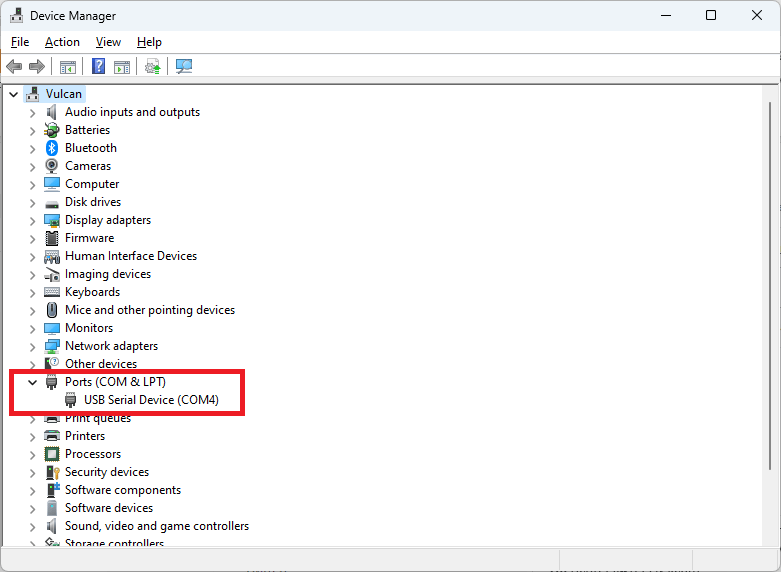
I made a Picoprobe and attempted to debug my code, but things were not as straight forward as they could have been, which resulted in many hours waisted.

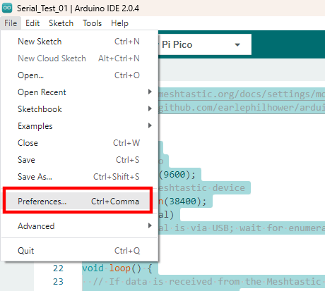
I had followed the instructions in the getting-started-with-pico.pdf guide and used the Windows Pico SDK, but could not get debugging to work in Visual Code or the Arduino IDE. I was nearly ready to setup another PC with Linux and give that a go as I had seen folks saw that just works with no issues. I’m running Windows, which I assumed was part of the issue. I saw another Windows user who was very frustrated as well and stating that it seemed they were the only ones testing/using this in Windows. They eventually got it working although they could not figure out the root cause. Unfortunately I too got it working and have no clear indication of what the root issue was but I have an idea that there is an issue with the Windows setup scripts that needs to be addressed. If someone has Visual Code and/or Arduino IDE installed before installing the SDK, they will have issues. This may not be the fault of the SDK, it could be with the Visual Code and Arduino IDE setup but I suspect it is indeed the Pico SDK setup on Windows that is the issue.

Out of frustration, I reinstalled the Windows Pico SDK and checked Visual Code and the Arduino IDE. Magically, Visual Studio code worked but the Arduino IDE still failed. I then uninstalled the Arduino IDE, then restarted the PC. Once the PC restarted, I deleted the C:\Users\<user id>\AppData\Local\Arduino15 and C:\Program Files\Arduino IDE folders to clear out anything that was already configured. I then reinstalled the Arduino IDE and tried again and the Arduino IDE worked too.

There really is a problem with the Pico SDK but it will be difficult to fix unless someone can figure out what changed from the problem install and the fixed install. Unfortunately, I did not capture anything before so I cannot tell what went wrong.

In the end, once debugging was working, I was able to step through my code and found the issue in about 2 minutes. Too bad the debugging fiasco caused several days of wasted time trying to get the debugging working.

Categories
AI Project Raspberry Pi Pico Web Application Development

Quick Update

Just wanted to drop a quick update as I have not been able to post for the past few weeks. I am working on a couple of projects that I plan to write about shortly.

Speech Timer Clock

I have been working on a speech timer clock for my Toastmasters Club. I took an alpha version to a club meeting to get some feedback and took the feedback and have been making improvements to it. Below is a quick video showing a little of the clock’s operation.

Speech timer showing demo of 1 to 2 minute speech

Artificial Intelligence (AI)

I looked into CodeProject.AI Server and found it very easy to use and useful. I plan to write some examples and corrected examples that are posted on CodeProject website. I have started a GitHub Repository for the examples at https://github.com/richteel/AI_Sample.

Categories
Arduino Project Ideas Raspberry Pi Pico

Raspberry Pi Pico with Arduino IDE

The Raspberry Pi Pico may be programmed in the Arduino IDE. There are three board libraries available but I found that the one written by Earle F. Philhower, III works best. Below are the steps that I took to get the example blink sketch loaded on the Raspberry Pi Pico.

  1. In the Arduino IDE, open the Boards Manager
  2. Type “Pico” in the search box
  3. If the “Arduino Mbed OS RP2040 Boards” is installed, click the “Remove” button to uninstall it
  4. If the  “Raspberry Pi Pico/RP 2040” is not installed, click the “Install” button to install it
Boards manager in the Arduino IDE
  1. Connect the Raspberry Pi Pico to the PC through the USB Port
  2. In the Arduino IDE menu, select the “Raspberry Pi Pico” board by going to Tools > Board > Raspberry Pi RP2040 Boards(3.2.0) (in Sketchbook) > Raspberry Pi Pico
Selecting the Raspberry Pi Pico board
  1. In the Arduino IDE menu, select Tools > Port from the menu
    • If this is the first time connecting the Raspberry Pi Pico to the PC, select UF2 Board
First time programming, select UF2 Board
    • If this is not the first time, then a list of COM Ports are available. Open the Device Manager to see the available COM Ports and determine which one is the Pico board. You may unplug the Pico Board, wait for the Device Manager to refresh with one less COM Port, then plug the Pico board back in. Note, which new COM Port appears, that will be the one to select in the Arduino IDE.
Device Manager showing the Ports
Port, select the correct COM Port
  1. Open the example “Blink” sketch from the menu File > Examples > 01. Basics > Blink
  2. Click the “Upload” button in the Arduino IDE to load the sketch onto the Pico board
    NOTE: You may see several warnings about whitespace. These warnings may be ignored
Successfully uploaded sketch
  1. You should see the LED on the Pico board flashing once the sketch is uploaded

Hopefully, this gets you up and running. It is always a good idea to run the example blink program first when configuring a new board. It lets you know right away if things are working as expected. Once that works, then move onto your code.

Categories
Android Arduino Meshtastic Microcontroller Project Ideas Raspberry Pi Pico

Meshtastic Serial

I wanted to see about connecting a Raspberry Pi Pico to a LillyGo TTGO T-Beam v1.1 device. I noticed that Meshtastic supports serial communications, so I decided to give it a go to see how it worked.

There are several serial modes but the ones that seem the most useful are TXTMSG and PROTO. First attempt will be with the TXTMSG Mode as that seems straight forward. Once the TXTMSG Mode is working, I will look into how to use the PROTO Mode.

Wiring

We need to connect the grounds between the two devices, then connect the transmit (TX) from one to the receive (RX) of the other device. Below is a table showing the connections used in my setup.

T-BeamPico
RX pin 13TX pin 1 (GP0)
TX pin 14RX pin 2 (GP1)
GNDGND
T-Beam and Pico wiring
Wiring between T-Beam and Raspberry Pi Pico

Meshtastic Setup

Meshtastic firmware was installed using the Web Installer at https://flasher.meshtastic.org/. The T-Beam came with Meshtastic preinstalled. You may need to use another method to install the firmware if the Web Installer does not work.

Meshtastic Web Installer

T-Beam TEXTMSG Mode

Once Meshtastic has been installed on the T-Beam device and connected to the Android or Apple application, go to the Module Settings to setup the serial connection on the T-Beam device. The Module Settings is accessed by clicking on the kebab menu (aka three vertical dots menu) and selecting “Module Settings”.

kebab menu
Kebab Menu
Module Settings menu item

Once the Module settings are displayed, scroll down to the “Serial Config” section and set the following items.

  • Serial enabled: turn on
  • RX: Set it to the T-Beam pin number for receive, which is 13 in my setup.
  • TX: Set it to the T-Beam pin number for transmit, which is 14 in my setup.
  • Serial baud rate: May leave it at the default setting or set it to “BAUD_38400”. I think it is best to set it as the default baud rate may change in other versions. I believe I read that it did change in the past.
  • Serial mode: Set it to TEXTMSG
  • Once everything is set, click the “Send” button.
Serial Configuration

Pico Arduino Code

The Pico code is written in C++ using the Arduino IDE. It is necessary to configure use the Pico Board provided by Earle F. Philhower, III. First, add the URL, https://github.com/earlephilhower/arduino-pico/releases/download/global/package_rp2040_index.json, to the Additional Boards Manager URLs by going to File > Preferences in the menu.

Arduino Preferences Menu Item
Arduino IDE Preferences

Click the icon to the left of the “Additional boards manager URLs” entry. Add the URL to the a new line in the textbox and click the “OK” button.

Additional Boards Manager URLs

Open the boards manager by clicking on the boards manager icon, type “Pico” in the search textbox, and install the board, Raspberry Pi Pico/RP2040 by Earle F. Philhower, III.

Boards Manager
Boards Manager

Once the board is installed, you may select it from the boards dropdown selection in the IDE, when the Pico is connected to the PC.

Pico selected in the boards drop-down list
Raspberry Pi Pico selected in the boards drop-down list
/*
  Sample code to allow the Pico to act as a serial bridge between the PC and the Meshtastic device.

  Data sent to the Pico using the Arduino Serial Monitor, PuTTY, or other terminal software is sent
  to the Meshtastic device over the Pico UART0/Serial1 connection. Any data received from the Meshtastic
  device to the Pico is relayed to the PC over the Pico's serial over USB connection.

  REFERENCES:
    - https://meshtastic.org/docs/settings/moduleconfig/serial
    - https://github.com/earlephilhower/arduino-pico/discussions/210
*/

void setup() {
  // PC to Pico
  Serial.begin(9600);
  // Pico to Meshtastic device
  Serial1.begin(38400);
  while (!Serial)
    ;  // Serial is via USB; wait for enumeration
}

void loop() {
  // If data is received from the Meshtastic device, send it to the PC over the USB connection
  if (Serial1.available()) {
    String receiveMessage = Serial1.readString();
    Serial.print("Message received on Serial1 is:  ");
    Serial.println(receiveMessage);  // Send to serial monitor
  }

  // If data is received from the PC, send it to the Meshtastic Device
  while (Serial.available()) {
    int inByte = Serial.read();
    Serial1.write(inByte);
  }
}

Upload the code to the Raspberry Pi Pico. Once the code is loaded, open the serial monitor and type some text and hit enter. The message will be received on the other node(s).

Sending message from PC
Message received on other node

Sending a message from another node, will be received and shown in the serial terminal.

Sending message from another node
Receiving message on PC

Now the simple TEXTMSG is working, we can try to get the PROTO working. The PROTO mode is interesting as it may be possible to configure the Meshtastic device, and query it for additional information. I will look into the PROTO Mode in the near future.

Categories
Project Raspberry Pi Pico

Dual Volt Amp Meter

Photo of the finished Dual Channel Voltage and Current Monitor reading two USB voltages and loads

Overview

This writeup is from the GitHub pages for the VoltsAmpsLogger project and from the hackster.io project page. The code is in the VoltsAmpsLogger GitHub Code Repository

The Dual Channel Voltage and Current Monitor project was created as I needed a way to look at the voltage and current going into an Adafruit Powerboost 1000c module and through the soft switch circuit that I built from Mosaic Industries Raspberry Pi ON/OFF Power Controller. I wanted to be able to monitor the voltage and current coming out of the controller and going into the Raspberry Pi.

The project is based on the Adafruit INA219 High Side DC Current Sensor Breakout and a Raspberry Pi Pico. The Raspberry Pi Pico is a bit overkill for this project, but I have a few on hand so that is what I choose to use.

Hardware Build

Parts List

Next Steps/Going Further

The data transfer rate is extremely slow. It is good enough for what is being done here but it would be nice to capture more data points over the same period. Right now, the rate is about one set of measurements per minute. (It takes about 1.2 seconds to send one set of measurements.) One way to speed this up would be to move away from JSON and sending tab delimited data. I may create another version of the Raspberry Pi Pico and Windows software to send delimited data and see if there is an improvement. I would expect to get 4 to 5 times as many measurements in the same amount of time. It still is not very fast, but it would be an improvement.

References

External Project Pages

Categories
Project Psion Raspberry Pi Pico

Re-creation of Psion Organiser II

In 1984, Psion launched the first practical pocket computer, the Psion Organiser I. Psion followed up with the Psion Organiser II.

Andrew Menadue has a project which recreates the Psion Organiser II with the Raspberry Pi Pico and ESP32-WROOM-32. He has several videos on YouTube and some GitHub repositories. Andrew was nice enough to send me a set of boards, which I’m in the process of building.

Bill of Materials

The bill of materials is an Excel document located on GitHub.

Power Supply

Categories
Project Raspberry Pi Pico

Armachat

I have been working on the Armachat project by Peter Misenko. I rewrote the code to implement functions that Peter had not completed and added a few more. Some of the added features include:

  • Implemented detection of a long keypress
  • Dedicated keys when not in the editor
    • Q – Toggle the keyboard backlight
    • A – Toggle the display backlight
    • V – Increase volume / Long keypress to decrease volume
    • B – Increase display brightness / Long keypress to decrease display brightness
  • Ability to receive messages in all screens including editor
  • Validation of editor input
  • Confirmation prompts

I have been working on an issue with editor text input. The display update procedure takes 400 to 500 milliseconds which causes an issue as keypresses are dropped when typing quickly. Initially it was taking nearly 1 second to update the screen so some improvement has been made but it is still not good enough. I continue to work on improving the screen draw time and may deploy a few things to allow all keys to be detected and handled.

Another area for improvement is the long keypress detection. I noticed that removing the long keypress detection speed up the code enough to catch all key presses however the added functionality that the long keypress provides is too much to ignore.

GitHub locations for Peter’s code and my rewrite.