I have been trying out the UGREEN HDMI Video Capture Card and it works well for my use case. I use it to capture the screen of the Raspberry Pi and PC screens.
You may wonder why you may want to use the device to capture a PC screen, but there are several reasons. The first use case is to capture images and videos of BIOS settings. Another is for capturing screen captures or videos of a PC recovery process. Lastly is to capture the installation of software that prompts the user to accept a security dialog that is not accessible to screen capture software.
Thee UGREEN HDMI Video Capture Card may be used to capture game play from gaming consoles with HDMI output. I have not tested game play capture but have tested capturing the screens of Linux and Windows systems.
Overall I’m very happy with the UGREEN HDMI Video Capture Card. I do feel funny calling it a card rather than a device as it is not a card that is connected internally in the PC but that is the name given to it
It provides pass-through capability with no noticeable lag. If you play a video game it may be possible to notice a lag but in my use, I did not notice a lag when typing. It was very responsive.
The device has an attached USB C cable that cannot be removed. It does come with a USB C to USB A adapter. The only issue i have is being able to tell which port is the input and which is the output. The text is very difficult to read. You can read it if the lighting angle is just right. It would have been helpful if the text had more contrast with the color of the case. This is a minor issue though. I would recommend the UGREEN HDMI Video Capture Card if you have thee need to capture HDMI video.
Below is a video review of the UGREEN HDI Video Capture Card.
VIDEO
Below is my Amazon Affiliate link to the UGREEN HDMI Vide Capture Card.
HyperGear Fabrix2 Portable Bluetooth Wireless Speaker
I recently reviewed a Bluetooth Speaker on Amazon and wanted to post some information about it. I did not give the speaker a great review even though it had good sound quality. Below is the review posted on Amazon.
Heading: Obnoxiously loud every time it is turned on
The design of the speaker looks very nice and it has good sound quality. I’m not an audiophile so you may think differently if you are. The speaker is very loud, so this would be useful for a large gathering of friends.
Now the bad, I had seen other reviewers comment about it being at high volume when it is turned on. I thought it may be nothing but a minor inconvenience but I soon learned that you don’t want to turn it on if others are sleeping or you do not want to disturb them. People will know when you turn it on. If the speaker respected the last volume setting or just started at a lower volume I could give it additional star(s), but the volume issue is too big of a issue. It is a nice looking and sounding speaker though.
Teardown
I did a teardown of the speaker to see if it was possible to modify the firmware on the speaker to fix the issue with it starting at max volume. Below are some photos from the teardown. There are multiple photos of the same chip or board as I was attempting to read the part numbers on the integrated circuits. I have included all the photos in case someone is interested and one photo works better than another.
Analysis
The IC that I focused on was the one marked AS24C093918-65E4. I could not find anything with that particular part number or any reduction of the marking but I did find some promising posts. One post pointed me to the manufacture, which is Zuhai Jie Li. I searched the site but did not find any reference to any ICs with a similar part number. I assume that the IC may be discontinued. I was able to find the GitHub repository and found some generic information related to the firmware on their ICs. It does appear possible to update the firmware.
I decided not to pursue this any further as all the documentation is in Chinese and I would need to determine how to procure the USB programmer mentioned in the documentation at https://doc.zh-jieli.com/Tools/zh-cn/dev_tools/forced_upgrade/upgrade_and_download.html. While it appeared to be doable to create new firmware and update the HyperGear Bluetooth Speaker, it simply was not worth the effort.
USB Programmer and Jie Li Technology’s prototype or development board.
I suspect that HyperGear simply outsourced the development and manufacture of this Bluetooth speaker and the lowest bidder won. They delivered a product that worked but failed to be acceptable by this end-user.
This weekend, I looked at replacing my current Linksys router with a newer 6e Mesh MR7500 router. I’ve been disappointed with Linksys not providing support for routers that are only a few years old but decided to continue with them as I’m familiar with how to configure them.
I found that the configuration of the MR7500 was straightforward. I was able to configure it as needed for my network. I was not impressed with the range as my older router has no problem connecting throughout the house but the newer MR7500 dropped off very quickly and was unusable through much of the house. I returned the MR7500 due to the poor performance of the Wi-Fi network.
I’m currently looking into the Synology routers as they look like they may provide some additional benefits that the Linksys routers cannot provide. I would like to look into using VLANs to separate network traffic to prevent network broadcast storms and provide some isolation for my IP Phones and Cameras as well as other IoT devices. I also like the support that Synology provides. I’ve been using Synology NAS devices for many years and even my older NAS gets regular updates. In addition, their customer support is very good. One time there was an issue with an update and the configuration of my NAS. I needed to reach out to customer support and after going back and forth a bit, they were able to determine the cause of the issue and helped me resolve it. Typically I get frustrated with customer support as they are following a script and it takes a long time to get to someone who can help me with my issue. The initial contact was somewhat similar but it did not take long to have my issue escalated to someone who could help me resolve the issue. Even though I mentioned some back and forth with tech support, it was just for the gathering of information.
The Synology routers are nearly double the price of the Linksys routers but I’m confident that Synology routers will continue to receive security updates for many years, which will make them worth the price. I do hope that they come out with a cheaper solution to extend the mesh network as I would like to have that option. I am concerned that the Synology router may not have any more range than the Linksys MR7500 had as they may be using the same radio or it may be the design of the radios supporting so many different bands. Even if this is the case, the ability to make use of VLANs to separate network traffic may make it worthwhile.
Ubiquiti routers and equipment are another option but the price point may be higher than Synology. The advantage of Ubiquiti is the management software allows for easy configuration of the entire network.
I would like to hear from you if you have experience with your home network using Synology or Ubiquiti routers and networking equipment. Please comment below.
All links to Amazon product pages are Amazon Affiliate Links. Any purchases made through these affiliate links help support me to continue produce content.
We will be traveling soon and one of the things that I am terrible at is overpacking, particularly with my electronic gadgets. I have a desire to reduce what I pack and one area that I’m focusing in on for our next trip is the cables. The devices that I typically travel with, use various USB charging cables. My devices use USB C, micro USB, mini USB, and Apple’s USB lighting cables. The chargers also have USB A and USB C connectors. That is a combination of 2^4 or 16 combinations of cables.
In addition to powering my devices, I like the option to connect to an HDMI monitor if one is available or I bring one along. The addition of HDMI increases the cable count as there are three types of HDMI connector: HDMI, mini HDMI, and micro HDMI. In addition to the three types of HDMI there is the option of USB C to HDMI.
As you can see, it is very easy to pack way too many cables on a trip if you want to be able to support these various options.
There is an option to support all of these combinations while carrying a small number of cables. The option is to only pack USB C cables with adaptors. The only option not covered is the HDMI Cable but as most devices support Display over USB C, this is not an issue. One way around this limitation is to use a wireless HDMI adaptor.
Travel power kit with USB Power Adapters, USB C cables, and USB C adapters
The image shows the items that I have in my kit. Links are affiliate links to Amazon products. (paid links)
It may be possible to travel with less, by carefully planning what is needed and carrying cables that will work with just the devices you have. Unfortunately that typically does not work for me. I usually get asked if I have a cable for another device that someone else brought or I forgot about the one device that still has mini USB. Being able to adapt to nearly any need is best and the ability to only use USB C cables will make it much easier. I hope you find this useful and if like me, you find you may not always have the cable you need, you too will travel with a similar assortment so you always have the cable you need.
There are many topics this week to cover, thus the reason for the non-descript title. Some of the things that have come up this week are Psion and Ericsson repairs, ChatGPT and DeepSource, and Agile2023.
Psion and Ericsson repairs
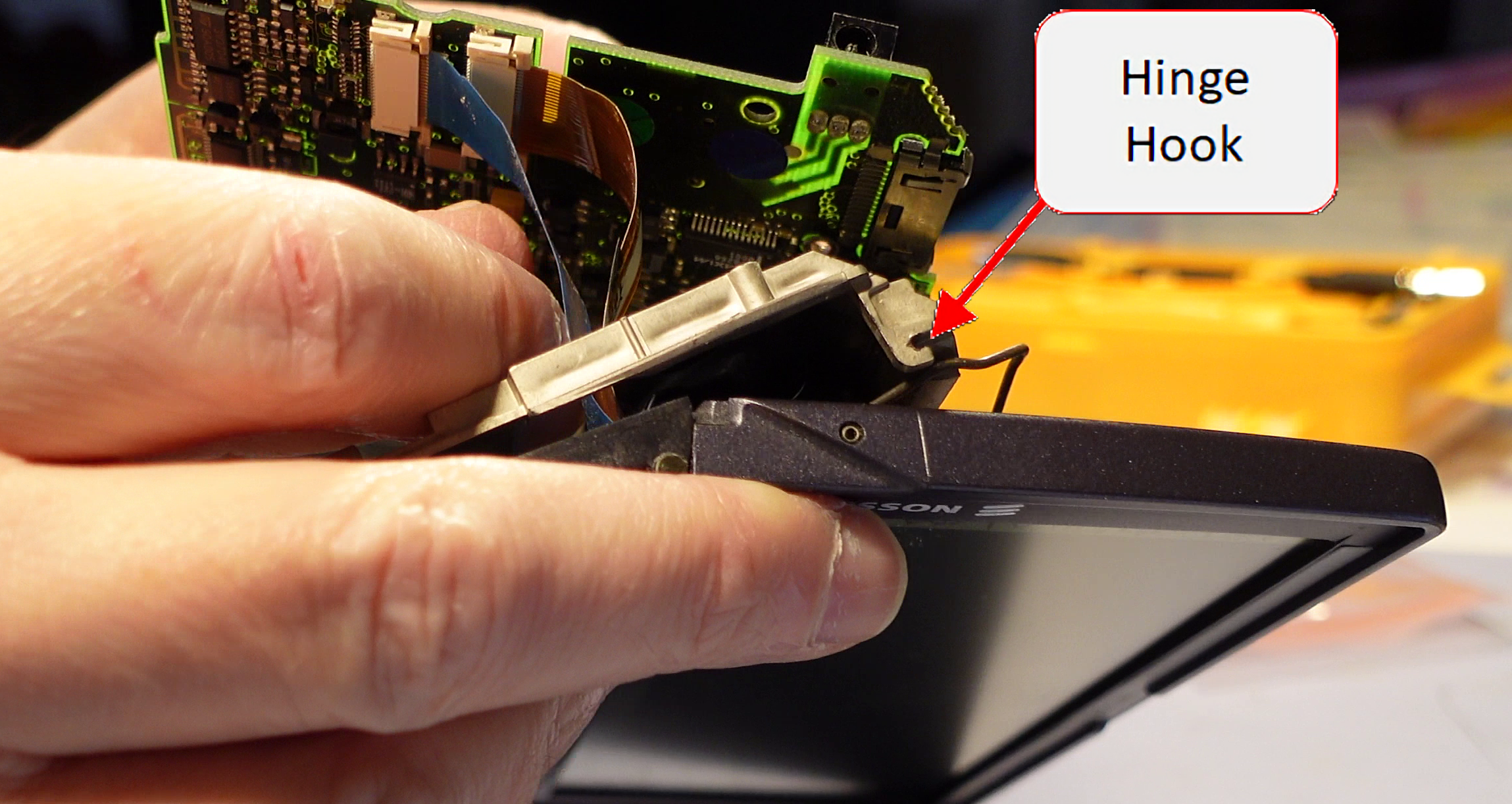
I was able to carryout another screen cable repair this week on the Ericsson MC 218. The MC 218 had the hooks in the back for the lid hinge so this repair resulted in a good as new repair. It did pose a challenge as the hinge is really not designed to be put in place while connected to the screen. I feared that I was going to break the plastic hooks so I worked to remove the pins holding the wire hinge from the screen. It was not easy and after I removed them, I saw that doing so caused a different challenge. The pins holding the wire hinges in place are actually spring metal wound up into a pin shape. This made them difficult to put back into place. The removal of the pins did make it much easier to get the wire hinges over the plastic hooks without breaking them, but I do not recommend doing that. If I carry out this repair again in the future, I plan to figure a better way to choregraph putting it all back together without breaking the hooks.
I feel that the terminology that I’m using to describe the hinge mechanism on the Psion 5 Series devices is not correct. If Martin Riddiford or anyone else in the know happens across this post, please add a comment below to let us know what the proper names for these are. Also a drawing with text pointing to them would be awesome as well.
I captured a video of the repair and hope to find some time shortly to edit it and post it to YouTube. I will post an update with a link to the video once it is available. In the meantime, here are some screen grabs from some of the video to show the hinge assembly and the spring metal pins referenced above.
Screen with showing wire hinges and spring metal pins.Unit with showing one of the two hinge hooks.A view of the other hinge hook.Another view of the hinge hook.
Hinge Repair
The hinge repair that I carried out last week, did not last long, which was not too much of a surprise. The metal pins bent and allowed the hinges to pop out from under the cover. I straightened the pins and used my 3Doodler, to add some PLA around the pins to give them a bit more strength so they hopefully will last a bit longer. The repair looked ugly but no one will see how bad I am at using the 3Doodler.
The opening and closing of the unit is very tight after the repair, which makes me a bit uncomfortable so I will take it easy when opening and closing the unit.
Hinge repair before and afterHinge repair before and after for the other side
ChatGPT and DeepSource
It looks like things may be starting to really take off in the Artificial Intelligence (AI) field. We are starting to see more and more application of AI in some of the products that we use. I had been following the latest news regarding ChatGPT and found it interesting that it was able to pass a law exam at two different universities. While it would not be at the head of the class, it is good enough to get a passing grade. This presents a lot of challenges for professors at universities.
I had not given it much thought until I saw a video, 10X Your Code with ChatGPT: How to Use it Effectively, by Dave Plummer showing how ChatGPT could be used by software developers and others. He showed how he was able to interact with ChatGPT to develop a small software application and how we all need to start to understanding how to use the tool in our workflows.
I have seen that Visual Studio is now prompting me with code completion, based on my previous actions and where I’m at in the code. It is kind of freaky seeing the IDE basically writing code for you. There were times that it seemed to get in the way but most of the time, it was a real time saver. I’m sure it will get even better in the near future.
We may be at at point in time when AI will really start to have an impact in how we work and in our daily lives. Let’s just say that it has my attention now.
DeepSource
As I was trying ChatGPT, one very good use case popped out, and that is to do code reviews. Typically I am a lone developer and one of the biggest disadvantages of being a lone developer is your code is rarely code reviewed by anyone. ChatGPT did a fairly good job but the length of code it can code review is very limited.
Looking into ChatGPT led me to look into tools for Code Review. I found an article at GeekFlare, 6 Best Automated Code Review Tools for Developers. The article listed DeepSource as number 3. I looked into the other options and settled on DeepSource. It has great integration with GitHub so it scans code each time it is checked in. I was able to clean up my code fairly quickly.
I’ve made a recommendation to the DeepSource Team to incorporate AI for code reviews, particularly for us lone developers. We may be a few years away from being able to have a really good AI performing code reviews, but I think that is something we will see in the very near future.
Agile2023
I received some news this week that my submission for the Agile2023 conference was accepted. Now, I need to focus on polishing and practicing the workshop. This will be my first time presenting at a conference, so I’m nervous and excited for the opportunity. I hope it goes well and starts me down a path for the future.
I have a SainSmart 2.8″ TFT LCD Display Touch Screen a couple of years ago from MicroCenter. I want to use it on the Raspberry Pi and was surprised that no one has posted how to do this. I looked into this a bit and it looks like it should be easy enough. One of the things that throws folks off is the display is 16 bit verses 8 bit that is typically used on these displays. You can still use them with only 8 bits of data. Unfortunately SainSmart does not provide information on their product pages to allow their products to be used with anything other that their adapters or other products.
Here are some useful links that will be used in this writeup.
I purchased an LCD Shield for Arduino from eBay a few weeks ago. I wanted to do a review to help others to get the shield to run on their Arduino or other microprocessor.
Overall Impression
Works as stated and is a good value. I would recommend this shield if you are in the market for a low cost shield with buttons for user input. It is a great shield to get a project going.
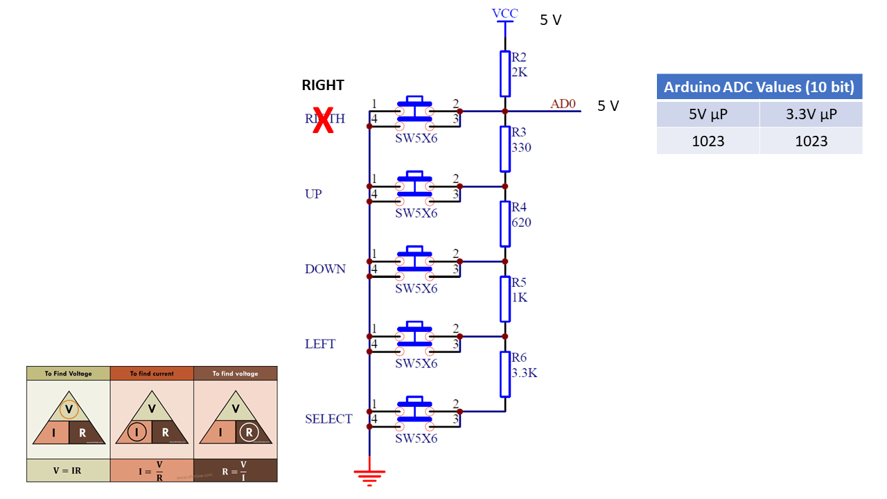
The shield uses one analog pin to determine which of the five switches the user has pressed. A series of resistors creates a voltage divider which in turn creates specific voltages for each switched pressed. The pins in use on the board are as follows.
Pin
Function
Pin
Function
Reset
Reset Button
10
LCD – Backlight
5V
Power
9
LCD – Enable
Ground
Ground
8
LCD – RS
A0
Buttons
7
LCD – D7
– SELECT
6
LCD – D6
-LEFT
5
LCD – D5
– UP – RIGHT – DOWN
4
LCD – D4
WARNING: The shield works on 5VDC. Not all Arduinos are 5V tolerant so you may damage your Arduino if you use this shield on an Arduino with a microcontroller running on 3.3V such as the Due. If you do not know what voltage the microprocessor on your Arduino is running at, check the Wikipedia article at https://en.wikipedia.org/wiki/List_of_Arduino_boards_and_compatible_systems.
Code for Testing
The following code was found on SainSmart’s website. It was modified slightly to monitor the value of the A0 pin over the serial connection with the PC.
/*
  The circuit:
 * LCD RS pin to digital pin 8
 * LCD Enable pin to digital pin 9
 * LCD D4 pin to digital pin 4
 * LCD D5 pin to digital pin 5
 * LCD D6 pin to digital pin 6
 * LCD D7 pin to digital pin 7
 * LCD BL pin to digital pin 10
 * KEY pin to analogl pin 0
 */

#include <LiquidCrystal.h>

LiquidCrystal lcd(8, 13, 9, 4, 5, 6, 7);

char msgs[5][16] = {"Right Key OK ",
                    "Up Key OK    ",
                    "Down Key OK  ",
                    "Left Key OK  ",
                    "Select Key OK" };

int adc_key_val[5] ={50, 200, 400, 600, 800 };
int NUM_KEYS = 5;
int adc_key_in;
int key=-1;
int oldkey=-1;

void setup()
{
  // open the serial port at 9600 bps:
  Serial.begin(9600);

  lcd.clear();
  lcd.begin(16, 2);
  lcd.setCursor(0,0);
  lcd.print("ADC key testing");

  //analogReadResolution(12);
}

void loop()
{
  adc_key_in = analogRead(0);    // read the value from the sensor
  Serial.println(adc_key_in);
  key = get_key(adc_key_in);  // convert into key press

  if (key != oldkey)   // if keypress is detected
   {
    delay(50);  // wait for debounce time
    adc_key_in = analogRead(0);    // read the value from the sensor
    key = get_key(adc_key_in);    // convert into key press
    if (key != oldkey)
    {
      lcd.setCursor(0, 1);
      oldkey = key;
      if (key >=0){
           lcd.print(msgs[key]);
      }
    }
  }
 delay(100);
}

// Convert ADC value to key number
int get_key(unsigned int input)
{
    int k;

    for (k = 0; k < NUM_KEYS; k++)
    {
      if (input < adc_key_val[k]) { return k; } } if (k >= NUM_KEYS)k = -1;  // No valid key pressed
    return k;
}
The code does not perform any debouncing of the button presses so you may need to modify the code if it becomes a problem in your project. Another limitation is the shield and/or the code will not be able to determine if more than one switch has been pressed. I have not tested this, but my hypothesis is that the switch with the lowest resistance will be detected.
Issue with 3.3V Adruino Boards
First off, read the warning above as you may damage your Arduino if the microcontroller is running at 3.3V.
After receiving the shield from the seller, frentaly , on eBay, I pulled out my Arduino Due as it happened to be the first Arduino board that I grabbed. I ran the above code and had some strange results. Pressing the “SELECT” button did nothing. Pressing the “LEFT” button registered “SELECT” was pushed. Likewise, pressing “DOWN” registered that the “LEFT” button was pressed. The “UP” and “RIGHT” buttons worked as expected. I sent a message to frentaly as I believed there was a problem with the shield. I then observed that the resistors for the voltage divider were the correct values so I pulled out a Mega board and ran the same test sketch. I found that the LCD button shield worked as expected on the Mega board. I did some investigating and found that the microprocessor on the Due board is running at 3.3V therefore the highest voltage that may be read on any analog pin is 3.3V. I went a bit further to get a bit more information.
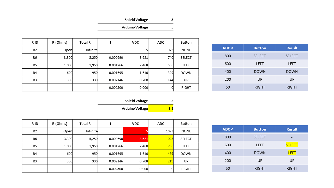
The table below provides some information regarding the ADC values reported on A0 with 5V and 3.3V microprocessor Arduino boards. In the table below there is not difference between no button pressed and the “SELECT” button being pressed.
Button
R ID
R (Ohms)
Total R
I
VDC
ADC 5V
ADV 3.3V
NONE
R2
Open
Infinite
5
1023
1023
SELECT
R6
3,300
5,250
0.000690
3.621
740
1023
LEFT
R5
1,000
1,950
0.001266
2.468
505
765
DOWN
R4
620
950
0.001695
1.610
329
499
UP
R3
330
330
0.002146
0.708
144
219
RIGHT
–
0.002500
0.000
0
0
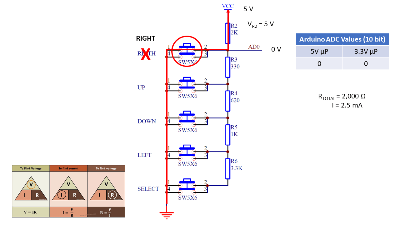
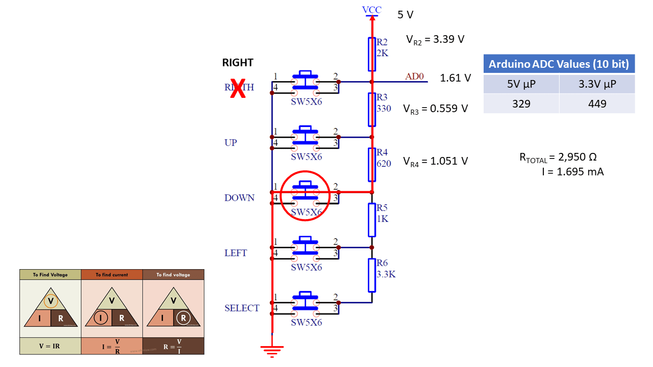
Here are some slides which provide some details on how the buttons work on the shield.
No buttons pressed
RIGHT button pressed
UP button pressed
DOWN button pressed
LEFT button pressed
SELECT button pressed
The schematic is from the SainSmart web page referenced above.
Below is the data presented above shown in a different format.
I have been contemplating learning Android development for a while now. I have dabbled in it in the past but never took a deep dive to create an application from scratch. I decided to go through a book from start to finish to see if that will give me what I need to finally take the dive.
The book is laid out really well and explains things much clearer than other books I have looked at over the years. I will say that Java development is still not much better than it was 20 years ago, at least on a Windows OS. I know some people will like to bash me for that comment but let me tell you about day one of working through the book and why Java still has a long way to go. (In retrospect after writing this, the blame is not really Java but the IDE. About 20 years ago, both were an issue but at least my issue is more to do with the IDE rather than Java.)
Installation of Android Studio seemed to go well. I got through the GeoQuiz example with no problems other than needing to use a physical device rather than the emulator due to Hyper-V being enabled on my system. I then worked on the challenge by copying the completed example and opening the copy. I made my changes and attempted to launch the application. I received an error that the apk could not be loaded or copied and a prompt was given to uninstall the apk with a warning that user data may be deleted. Since the application did not have associated user data, I clicked the button to uninstall the apk. Another error showed up in the log stating that the apk could not be copied or installation failed. (Sorry, I do not call the exact text.)
At this point, I assumed that the issue was with my device having the application installed from the sample so I decided to try the emulator. I was being a bit lazy so I clicked the link in the emulator selection to turn off Hyper-V. This change required a reboot so I let the PC reboot. On reboot, Windows 10 attempted to fix an error and stated that automatic repair failed to fix the issue. I attempted to turn Hyper-V back on from the command prompt but I was unable to do so from the Windows PE command prompt. I then decided to try turning off early anti-virus and the PC rebooted. Of course I was not happy about that especially since my AV software kept complaining that it could not reach the live-update site and other issues. Basically I had a mess to clean up. Once I finally got the OS squared away, I decided to go back to the challenge. Now Android Studio was having all kinds of issues. (All of these issues may be related to other attempts to boot back into Windows including restoring a previous restore point.)
I uninstalled Android Studio, deleted the files in the Program Files folder, rebooted, and reinstalled Android Studio. I was still having issues launching Android Studio. I finally found that I needed to delete the contents of the C:\Users\AppData\Local\Android\Sdk folder. I then needed to reinstall the SDK, emulator, and build tools. Once these were reinstalled, Android Studio behaved well as it did before. I attempted to run the application and the emulator launched so that was great news but I received the original error regarding the apk file.
I was at a loss but looked a bit more into the log file and it pointed me to a file in the C:\Users\Documents\AndroidStudioProjects\GeoQuiz – Challenge\app\build\intermediates\split-apk\debug\slices folder. I deleted all of the files in the folder but I still received the same message. This was getting quite frustrating so I decided to try deleting all of the files and folders in the C:\Users\Documents\AndroidStudioProjects\GeoQuiz – Challenge\app\build folder. I attempted to build and run the application again. Low and behold, this time the application launched in the emulator. Finally success.
With all of this said, I’m going to keep marching on. It is very frustrating to have the Android Studio behave this way but hopefully my rant here will help someone. If nothing else, it will serve as a reminder to myself what to do when this error occurs.
Here are some locations of note regarding where Android Studio places files. If you want to uninstall and reinstall Android Studio, you should uninstall, delete the following folders, and reinstall. (These may not be all of the locations but these are the ones I found.)
My Glowforge finally arrived this week. I pre-ordered it in October 2015 so it took a little over two years of waiting to finally get it.
I designed and printed the obligatory escutcheon for the print button. I chose to name my Glowforge Scotty in honor of James Doohan. His character was my inspiration for becoming an engineer in the first place so I felt it was fitting.
The escutcheon after being printed.
The escutcheon after removing the tape covering.
A few thoughts on the Glowforge interface.
The interface and workflow will take a bit of getting use to but I think it will be fine once I’m more familiar with it. At first I was getting frustrated as I created a PNG image to scale. When I imported it, I thought it was too small until I realized the scale is in inches not mm. Once I realized my error, I looked for an option to change it but could not find one. I attempted to find a way to scale it to the correct size but there is no option to type in the size or view the exact measurement. It is necessary to guess what size it is by looking at the ruler on the screen which is not very accurate. What I ended up doing was using the 1:1 scale printout and placing it in the Glowforge so I could attempt to scale it correctly. Once I did that, I could not figure out how to do cuts where I wanted them. I did some reading and found that an SVG is needed for cuts. I then used Inkscape to create an SVG from a modified image with only the cuts. This worked and I was able to scale it exactly. I then created another PNG file with just the engraving and uploaded both files. I still needed to scale the engraving but that was easy and not critical. Once everything looked good, I pressed the print button. The Glowforge performed the cuts but not the engraving. I then removed the cut image and clicked print again. This time the engraving was done. On my next print, I will need to see what I did wrong here so I do not make that mistake again.
Overall it was easy to use the Glowforge but I do have a few concerns. Firstly, a desktop application to prepare the print would afford a better setup experience. Secondly, it is not possible to print if your network connection is down for any reason or if Glowforge goes out of business. While it is nice to use a device this way, it does leave users vulnerable to the existence of the company and the health of the web servers.
The original PNG file I created.
A modified PNG for the cuts. This file could not be used for the cuts as PNG files may only be used for engraving. I needed to convert this file to SVG using Inkscape.
The modified PNG for the engraving.
Overall, I’m pleased with the Glowforge. I just hope that the company and the web-service run well for many years to come so I may continue to use the Glowforge.
BTW: The size of the escutcheon is 119.903 x 119.903 mm. I was not able to upload the SVG for the cuts so if you decide to use the PNG, you will need to convert it to SVG and resize it.
I have had a MyDIYCNC Machine sitting around for a few years now. I was having some problems with the controller boards so I set it aside and am just getting back to take another look at it. I found that one of the boards that was sent to me was indeed bad but MyDIYCNC no longer sells machines or parts. I then decided to go to Amazon and pick out a controller board to try. I picked the SainSmart CNC TB6560 3 Axis Stepper Motor Driver Controller Board & Cable. This board seems to work quite well. I have been having a bit of a time getting it to work properly in LinuxCNC but I have got it to home and move but it seems to be at 1/2 scale. I am still tweaking with the settings to see if I can get it to work 100%.
A few notes about wiring and hardware. The MyDIYCNC instructions refer to the motor which moves the Z axis carrier as the Y axis. It appears that it should really be the X axis and the table should be the Y axis. If it were the Y axis, the home position would be in the wrong corner of the machine. I played with the configuration a bit to see if I could get it to work as expected but I had no luck. Finally when I decided to try to swap the X and Y axes did home line up in the correct corner. I could have swapped A & B around on the Y motor and that may have reversed the direction of the motor but I did not want to go there. Swapping the axes made the most sense.
Here is a short video of a test of the CNC. The spindle has a ink cartage in it and is simply running the default LinuxCNC project. The drawing should be 5.3 inches wide but is only half that size.
Here are the settings for LinuxCNC.
Base Information
Machine Name: MyDIYCNC_inches
Axis configuration: XYZ
Reset Default machine units: Inch
Driver type: Other
Driver Timing Settings(The Stepper Drive Timing page on linux.org states that 150,000 ns should be used for all values however the current version of LinuxCNC has a max value of 100,000.)
Step Time: 100000
Step Space: 100000
Direction Hold: 100000
Direction Setup: 100000
Base Period Maximum Jitter: 9000
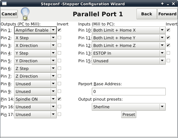
Parallel Port 1
Outputs (PC to Mill):
Pin 1: Amplifier Enable (Invert)
Pin 2: X Step
Pin 3: X Direction
Pin 4: Y Step
Pin 5: Y Direction
Pin 6: Z Step
Pin 7: Z Direction
Pin 8: Unused
Pin 9: Unused
Pin 14: Spindle ON (Invert)
Pin 16: Unused
Pin 17: Unused
Inputs (Mill to PC):
Pin 10: Both Limit + Home X (Invert)
Pin 11: Both Limit + Home Y (Invert)
Pin 12: Both Limit + Home Z (Invert)
Pin 13: ESTOP In
Pin 15: Unused
Parport Base Address: 0
Output pinout presets: Sherline (The value here is not important. It is actually used with the “Preset” button to load values.)
Options
Selections here really do not matter. I have not figured out how to use these yet. I may look into it more in the future.
Axis X
Motor steps per revolution: 800 (Steppers included with MyDIYCNC are 50 steps per revolution. The TB6560 board has the switches set for 1/16 microstepping. 50 x 16 = 800)
Driver Microstepping: 2.0 (Someone posted that 2 meant that microsteping was being used. I had this set to 32 earlier.)
Pulley teeth (Motor:Leadscrew): 1.0:1.0 (All axes are direct drive so they are all 1:1.)
Leadscrew Pitch: 20.0
Maximum Velocity: 0.4
Maximum Acceleration: 30.0
Home location: 0.125 This took awhile to get. If using the limit switches as home switches as well, we need to back the machine off so that the limit switches are not active when at home position. I choose to back them off 1/8 inch on all axes.)
Table travel: 0.0 to 5.5
Home Switch Location: 0.0
Home Search velocity: -0.05
Home Latch direction: Same
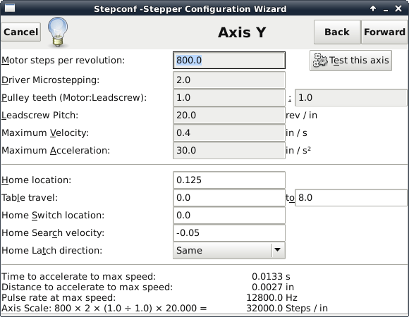
Axis Y
Motor steps per revolution: 800
Driver Microstepping: 2.0
Pulley teeth (Motor:Leadscrew): 1.0:1.0
Leadscrew Pitch: 20.0
Maximum Velocity: 0.4
Maximum Acceleration: 30.0
Home location: 0.125
Table travel: 0.0 to 8.0
Home Switch Location: 0.0
Home Search velocity: -0.05
Home Latch direction: Same
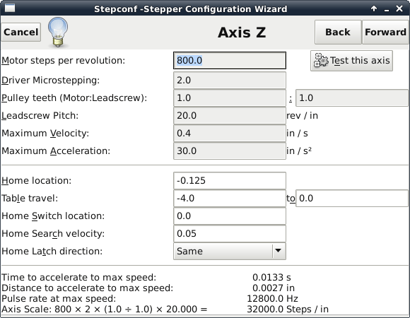
Axis Z
Motor steps per revolution: 800
Driver Microstepping: 2.0
Pulley teeth (Motor:Leadscrew): 1.0:1.0
Leadscrew Pitch: 20.0
Maximum Velocity: 0.4
Maximum Acceleration: 30.0
Home location: -0.125
Table travel: -4.0 to 0.0
Home Switch Location: 0.0
Home Search velocity: 0.05
Home Latch direction: Same
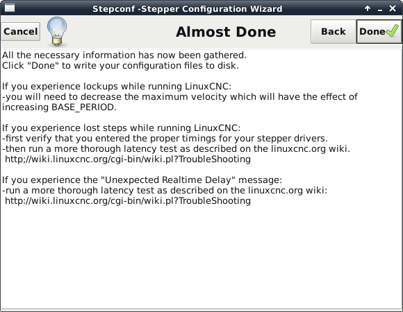
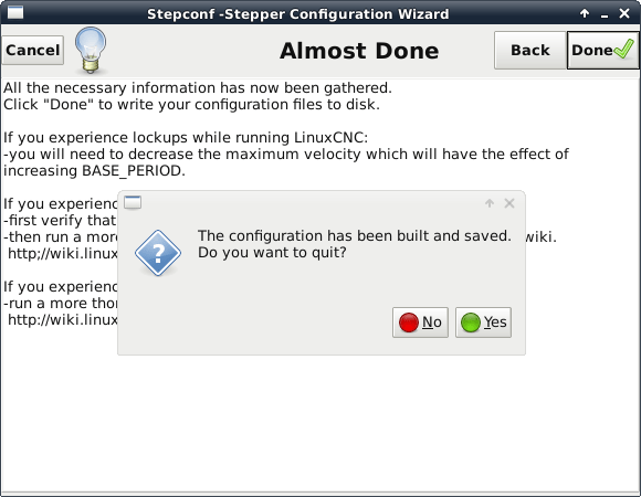
Almost Done
Do you want to quit?
Screenshot added for completeness
I plan to continue to look into what is going on with the scaling and settle on the correct settings or at least settings which will work.


You must be logged in to post a comment.