I would like to add more videos to the blog. One of the problems that I have had is the time it takes to perform post processing on videos to add different sources and information. I found the Open Broadcaster Software application and started messing around with it and found that it is quite good, once you get use to how it works. Here is my first attempt at creating a video with the software.
BTW: Yes, I totally ripped off some ideas from Adafruit. I’m not too creative so I copied what I like. I will attempt to change it but it is tough as Limor and Phil have created a very nice format for the shows that Adafruit produces. I also like Ben Heck and Dave Jones (EEVBlog) videos as well but I seem to watch more of the videos Adafruit puts out.
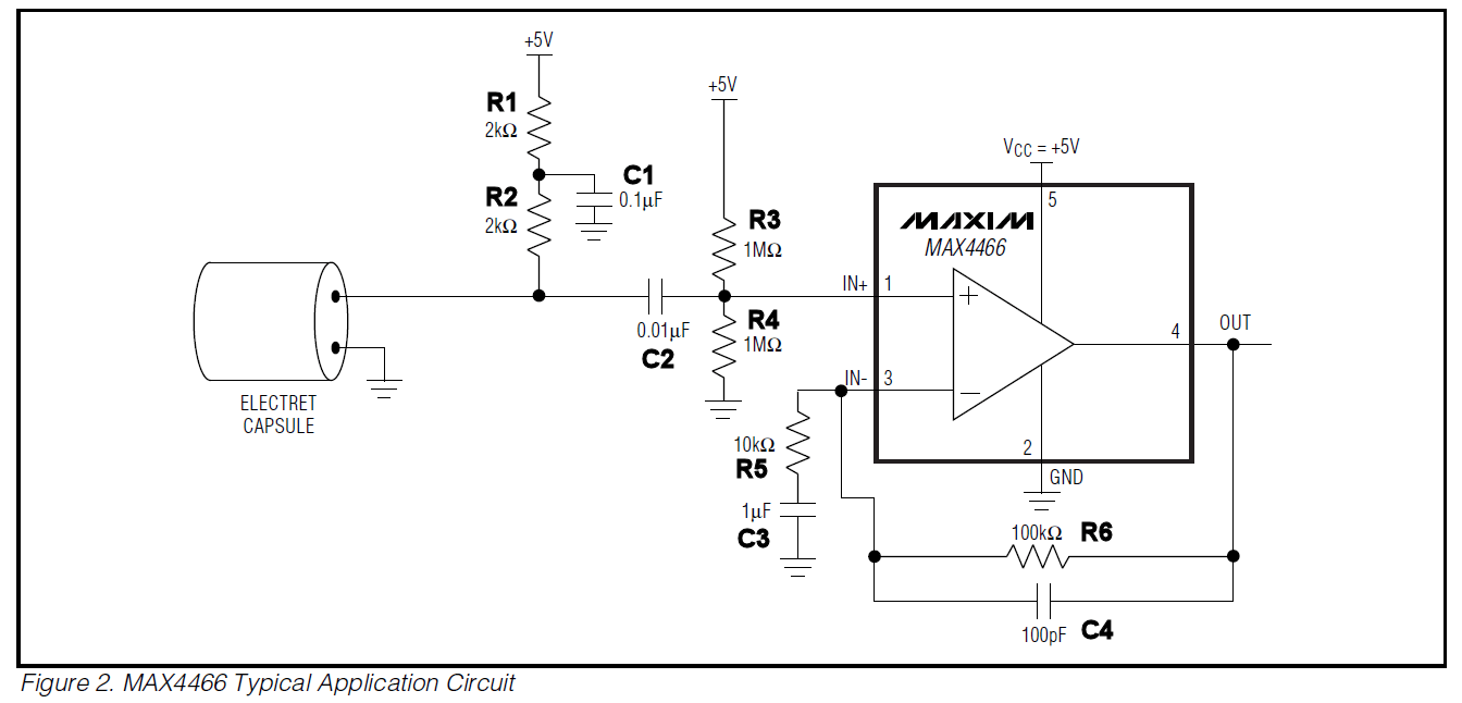
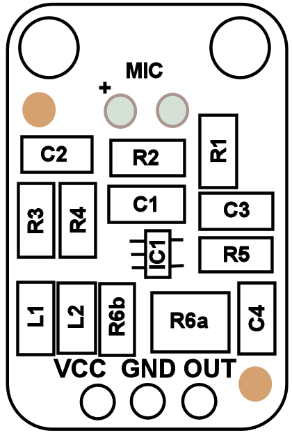
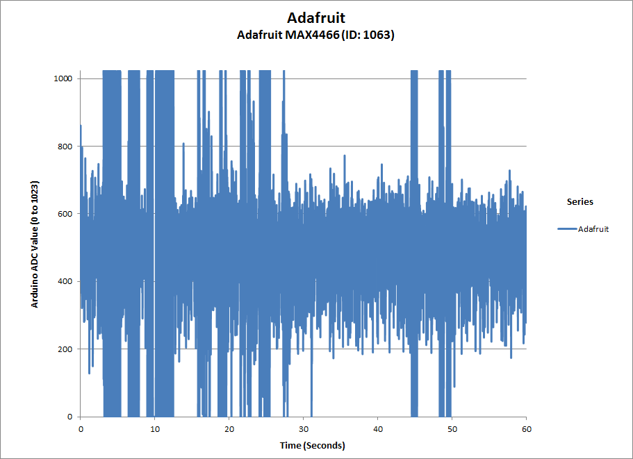
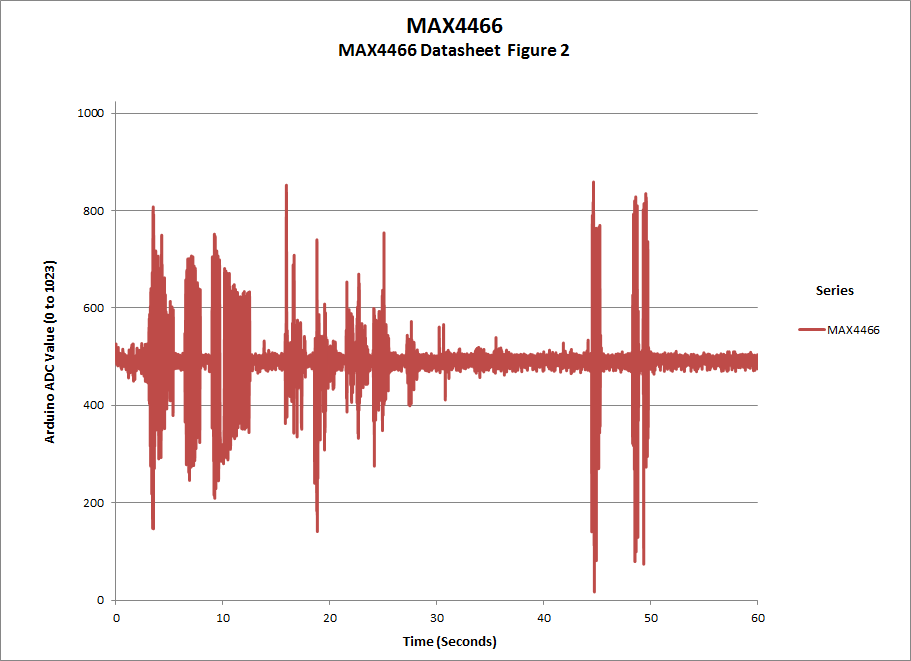
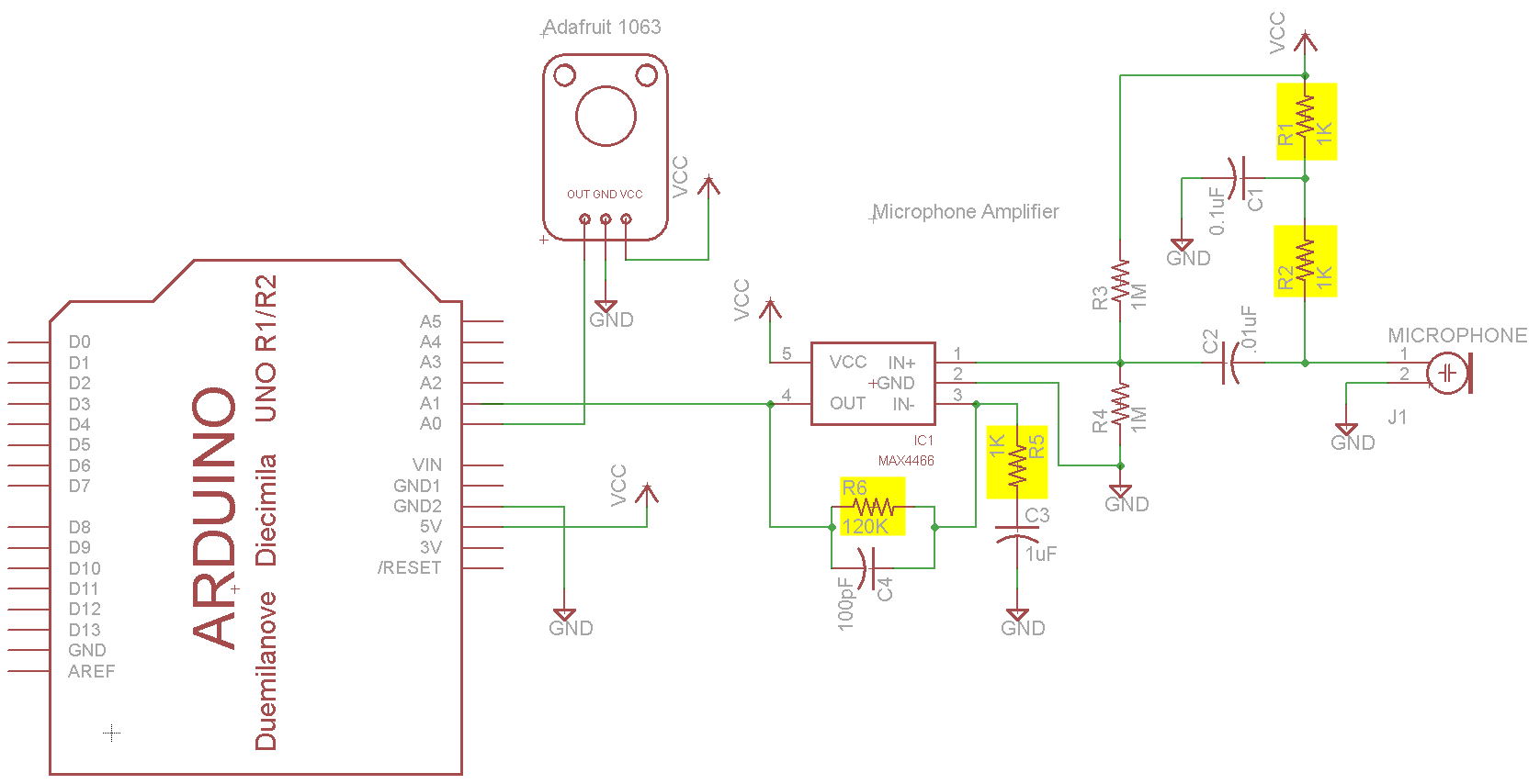
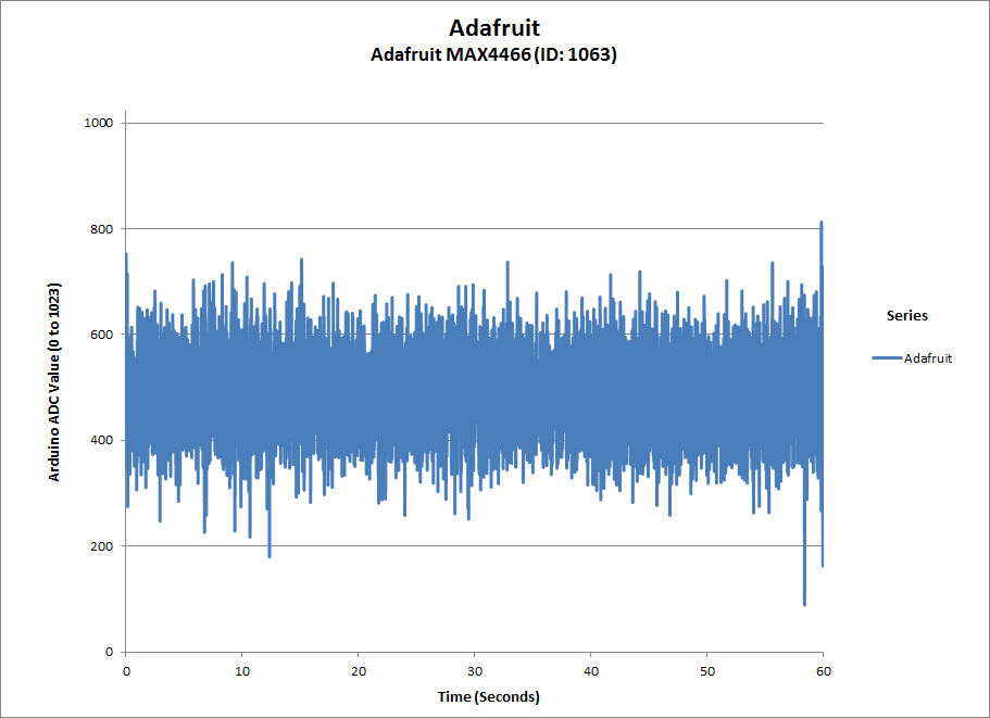
I purchased Adafruit’s Electret Microphone Amplifier – MAX4466 with Adjustable Gain (1063) and wanted to incorporate the circuit into a board that I am making to make a sound responsive decorative light. I saw a post from Adafruit that stated that the schematic was taken directly from the datasheet however looking at the component values on the board, it was obvious that some values had been changed. After a bit of reverse engineering of the board, it was confirmed that the schematic is indeed Figure 2 from the datasheet.
Component Listing (Note Capacitor Values taken from Datasheet Schematic and not verified)
IC1 – MAX4466
R1 – 1KΩ
R2 – 1KΩ
R3 – 1MΩ
R4 – 1MΩ
R5 – 1KΩ
R6a – 100KΩ
R6b – 22KΩ
C1 – 0.1µF
C2 – 0.01µF
C3 – 1µF
C4 – 100pF
L1 – Ferrite Bead
L2 – Ferrite Bead
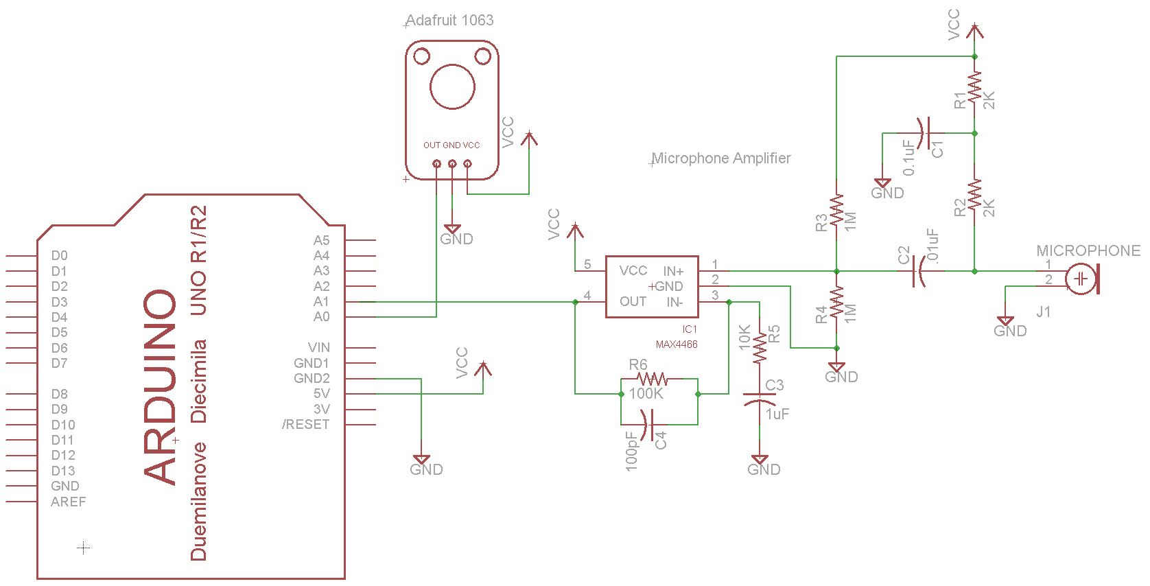
I wrote a simple program on the Arduino to capture 100 points of data per second for one minute and write the results to the serial output.
// Based on the Adafruit Trinket Sound-Reactive LED Color Organ
// http://learn.adafruit.com/trinket-sound-reactive-led-color-organ/code

#define MIC0_PIN 0 // Microphone is attached to Trinket GPIO #2/Gemma D2 (A1)
#define MIC1_PIN 1 // Microphone is attached to Trinket GPIO #2/Gemma D2 (A1)
#define DC_OFFSET 0 // DC offset in mic signal - if unusure, leave 0
#define NOISE 30 // Noise/hum/interference in mic signal
#define SAMPLES 60 // Length of buffer for dynamic level adjustment

int pointsPerSecond=100;
int captureMinutes = 1;
int delayMS = 1000/pointsPerSecond;
int datapoints=pointsPerSecond * captureMinutes * 60;
int curIdx=0;

void setup() {
 // put your setup code here, to run once:
 Serial.begin(57600);
 while (!Serial) {
 ; // wait for serial port to connect. Needed for Leonardo only
 }
 Serial.println(F("Idx\tAdaFruit\tMAX4466"));
}

void loop() {

 if(curIdx < datapoints)
 {
 // put your main code here, to run repeatedly:
 int adaFruitMic = analogRead(MIC0_PIN); // Raw reading from mic
 int max4466Mic = analogRead(MIC1_PIN); // Raw reading from mic

 Serial.print(curIdx);
 Serial.print(F("\t"));
 Serial.print(adaFruitMic);
 Serial.print(F("\t"));
 Serial.println(max4466Mic);

 curIdx++;
 delay(delayMS);
 if(curIdx >= datapoints)
 Serial.println("End of Sample");
 }
}
Here is the circuit diagram for the first test with values from the datasheet.
Test Schematic 1 – Values from datasheet
At first, I tried to use the values from the datasheet and noticed that the gain was not as high as the Adafruit module.
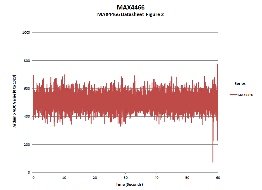
Adafruit (ID: 1063) and MAX4466 Typical SchematicAdafruit (ID: 1063) CaptureMAX4466 Schematic from Datasheet
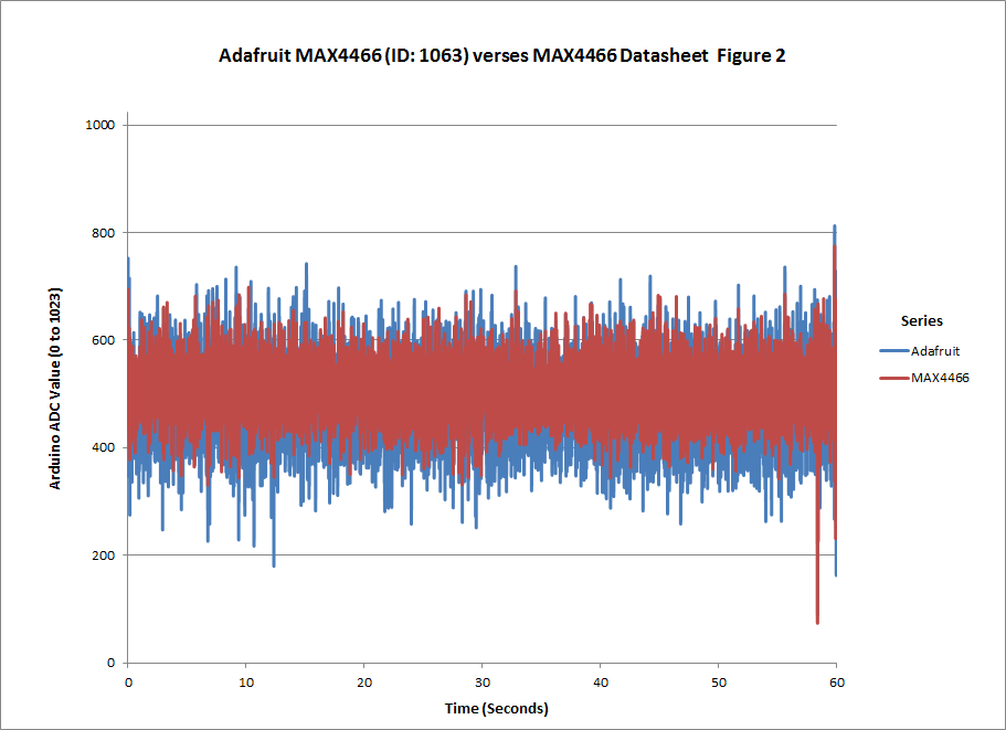
Modified values to be close to the values used by the Adafruit 1063 module. The results showed that the gain was much better so these values will be good enough for my application, If you need to use this for a different application where you need better performance, you may want to look into the RC values. By modifying the capacitor values, it may be possible to achieve a cleaner output.
Modified resistor values to match Adafruit 1063 moduleAdafruit (ID: 1063) and MAX4466 Typical Schematic modified valuesAdafruit (ID: 1063)MAX4466 Typical Schematic modified values
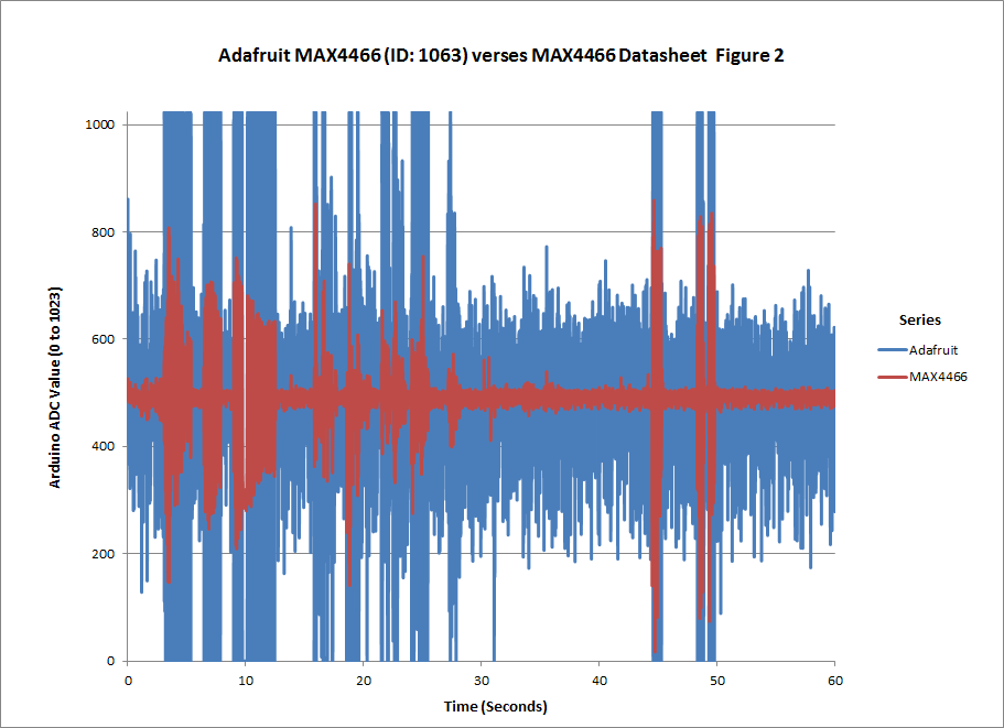
This is not a thorough analysis of the performance of these two circuits but as stated above, it was good enough to give me the performance that I needed. (Test with Datasheet Figure 2)
BTW: The values read by the Arduino ADC are between 0 and 1023. The signal is centered around 511 and has a noise level of ±50.
FYI: The gain for the circuit may be calculated as:
You can also see from the graphs that the amplifier is driven to saturation. For my application that is acceptable but it may not be acceptable for your application particularly if you are creating a purely audio application.
I wanted to grab some video of the Raspberry Pi booting up with the Raspbian “wheezy” distribution. To do this, I planned to capture the video on my PC by using a USB video capture device. I bought two devices from Microcenter in hopes that one would work reasonably well but I was disappointed with the results from both devices. I later purchased another device from Newegg which worked much better and is used for all of the initial screen captures of the Raspberry Pi.
First a review of the low cost devices
Other than the quality of the video, I was rather disappointed with the way they did not play well with other video capture software. Each comes with some video capture software but I wanted to use Corel’s VideoStudio Pro X4 or Windows Live Movie Maker. At first it did not appear that the hardware devices would work with either software but I was able to figure out how to use them with Corel VideoStudio Pro X4. The default input on the device is S-Video not composite. In Corel VideoStudio Pro X4, you need to select composite input in the Options > Video Properties.
Neither device would work in Windows Live Movie Maker. When the capture device was selected and an attempt was made to capture video, the following message would be displayed. “Sorry, Movie Maker can’t record audio or video from the selected device.”
Devices tested
Sabrent USB 2.0 Video and Audio Capture Device (USB-AVCPT)
DIAMOND USB 2.0 HD 1080 Game Console Video Capture Device (GC1000) USB 2.0 Interface
The Diamond GC1000 has much better quality however there are still some issues. The biggest issue is that it will not work with any software other than the included capture software. The good news is that the software works well. I did have a few issues at first but I was able to work through them and get it to work well. The other issue with the device is that the video displayed on the PC lags considerably from the live video. This is not too much of an issue and can be worked around by connecting a monitor to the output and working with that monitor rather than the video on the PC.
Sample video of the Diamond GC1000 – Composite Video with S-Video adapter (Now I connect to the Y jack of the Component Video)
Sample video of the Diamond GC1000 – HDMI
Conclusion
The bottom line is you get what you pay for, The cheaper devices I purchased from Microcenter work but the quality is not very good. I found them unacceptable for capturing video from the Raspberry Pi as the text was difficult to read in the captured video.
The Diamond GC1000 has much better video quality however there are still a few quirks that you need to deal with but they are not difficult to overcome and the resulting video is acceptable.
You must be logged in to post a comment.