The goal of the day is to get the Raspberry Pi and Arduino talking to each other over I2C.
I followed a few examples provided on the internet and was able to get the two to talk to each other. Just to be clear, the Raspberry Pi will be the I2C master and the Arduino will be the slave. One of the nice advantages to this configuration is that it is not necessary to do any voltage level shifting between the two devices. If you are not aware, the Raspberry Pi GPIO is at 3.3V and the Arduino is at 5V. If the Arduino were to supply 5V to any of the Raspberry Pi’s GPIO pins, the Raspberry Pi will be toast.
I followed the tutorial at http://blog.retep.org/2014/02/15/connecting-an-arduino-to-a-raspberry-pi-using-i2c/. Below are some of the high level steps.
- Download the latest Raspbian image from https://www.raspberrypi.org/downloads/raspbian/
- Unzip the file and write the image to the SD Card using Win32DiskImager from https://sourceforge.net/projects/win32diskimager/
- Once the Raspberry Pi boots, open a terminal window and run raspi-config to enable I2C Support
sudo raspiconfig

- Select “Advanced Options” from the menu

- Select “I2C” from the Advanced Options menu

Select “Yes”

Select “OK”

Select “Yes”

Select “OK”

”Select “Finish”

- Install i2c-tools
sudo apt-get update

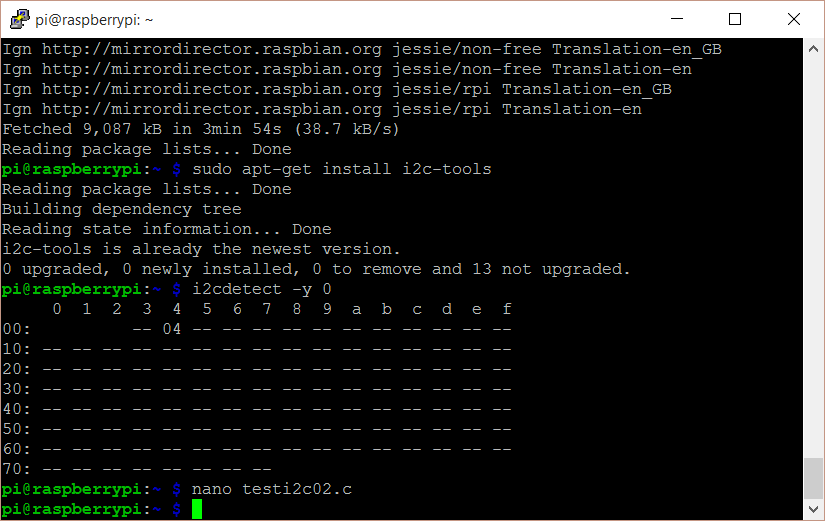
sudo apt-get install i2c-tools

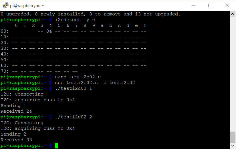
- Run i2cdetect to make certain that i2c-tools installed properly
i2cdetect –y 0
or
i2cdetect –y 1

If all worked well, you will see the following output

If there are devices connected to the I2C pins, you will see the devices listed as in this example.

- Wire up the Arduino and Raspberry Pi
Raspberry PI Arduino
GPIO 0 (SDA) <–> Pin 4 (SDA)
GPIO 1 (SCL) <–> Pin 5 (SCL)
Ground <–> Ground


- Upload Code to the Arduino
#include <Wire.h> #include "DHT.h" #define SLAVE_ADDRESS 0x04 #define PIN_DHT 4 #define PIN_PHOTORESISTOR A3 #define PIN_LED 1 #define DHTTYPE DHT11 // DHT 11 //#define DHTTYPE DHT22 // DHT 22 (AM2302), AM2321 //#define DHTTYPE DHT21 // DHT 21 (AM2301) int humidity = 0; int temperatureCelsius = 0; int lightReading = 0; int number = 0; unsigned long previousMillis = 0; const long interval = 1000; bool flashLed = true; // Initialize DHT sensor. // Note that older versions of this library took an optional third parameter to // tweak the timings for faster processors. This parameter is no longer needed // as the current DHT reading algorithm adjusts itself to work on faster procs. DHT dht(PIN_DHT, DHTTYPE); void setup() { pinMode(PIN_DHT, INPUT); pinMode(PIN_PHOTORESISTOR, INPUT); pinMode(PIN_LED, OUTPUT); digitalWrite(PIN_LED, LOW); dht.begin(); // initialize i2c as slave Wire.begin(SLAVE_ADDRESS); // define callbacks for i2c communication Wire.onReceive(receiveData); Wire.onRequest(sendData); } void loop() { unsigned long currentMillis = millis(); if (currentMillis - previousMillis >= interval) { previousMillis = currentMillis; if (flashLed) { digitalWrite(PIN_LED, HIGH); } ReadDHT(); ReadLightLevel(); if (flashLed) { digitalWrite(PIN_LED, LOW); } } } // callback for received data void receiveData(int byteCount) { while (Wire.available()) { number = Wire.read(); switch (number) { case 1: // Temperature in Celsius number = temperatureCelsius; break; case 2: // Humidity number = humidity; break; case 3: // Light Level number = lightReading; break; case 4: // LED On digitalWrite(PIN_LED, HIGH); flashLed = false; break; case 5: // LED Off digitalWrite(PIN_LED, LOW); flashLed = false; break; case 6: // LED Flash on read digitalWrite(PIN_LED, LOW); flashLed = true; break; default: break; } } } // callback for sending data void sendData() { Wire.write(number); } void ReadDHT() { humidity = 0; temperatureCelsius = 0; // Reading temperature or humidity takes about 250 milliseconds! // Sensor readings may also be up to 2 seconds 'old' (its a very slow sensor) humidity = dht.readHumidity(); // Read temperature as Celsius (the default) temperatureCelsius = dht.readTemperature(); } void ReadLightLevel() { int photocellReading = analogRead(PIN_PHOTORESISTOR); lightReading = ((float)photocellReading / 1023.0) * 100.0; } - Write the application on the Raspberry Pi
nano testi2c02.c

- Type of copy paste the following code
#include <string.h> #include <unistd.h> #include <errno.h> #include <stdio.h> #include <stdlib.h> #include <linux/i2c-dev.h> #include <sys/ioctl.h> #include <fcntl.h> #include <unistd.h> // The PiWeather board i2c address #define ADDRESS 0x04 // The I2C bus: This is for V2 pi's. For V1 Model B you need i2c-0 static const char *devName = "/dev/i2c-0"; int main(int argc, char** argv) { if (argc == 1) { printf("Supply one or more commands to send to the Arduino\n"); exit(1); } printf("I2C: Connecting\n"); int file; if ((file = open(devName, O_RDWR)) < 0) { fprintf(stderr, "I2C: Failed to access %d\n", devName); exit(1); } printf("I2C: acquiring buss to 0x%x\n", ADDRESS); if (ioctl(file, I2C_SLAVE, ADDRESS) < 0) { fprintf(stderr, "I2C: Failed to acquire bus access/talk to slave 0x%x\n", ADDRESS); exit(1); } int arg; for (arg = 1; arg < argc; arg++) { int val; unsigned char cmd[16]; if (0 == sscanf(argv[arg], "%d", &val)) { fprintf(stderr, "Invalid parameter %d \"%s\"\n", arg, argv[arg]); exit(1); } printf("Sending %d\n", val); cmd[0] = val; if (write(file, cmd, 1) == 1) { // As we are not talking to direct hardware but a microcontroller we // need to wait a short while so that it can respond. // // 1ms seems to be enough but it depends on what workload it has usleep(10000); char buf[1]; if (read(file, buf, 1) == 1) { int temp = (int) buf[0]; printf("Received %d\n", temp); } } // Now wait else you could crash the arduino by sending requests too fast usleep(10000); } close(file); return (EXIT_SUCCESS); } - Save the file by pressing <Ctrl> + o


- Exit the editor by pressing <Ctrl> + x

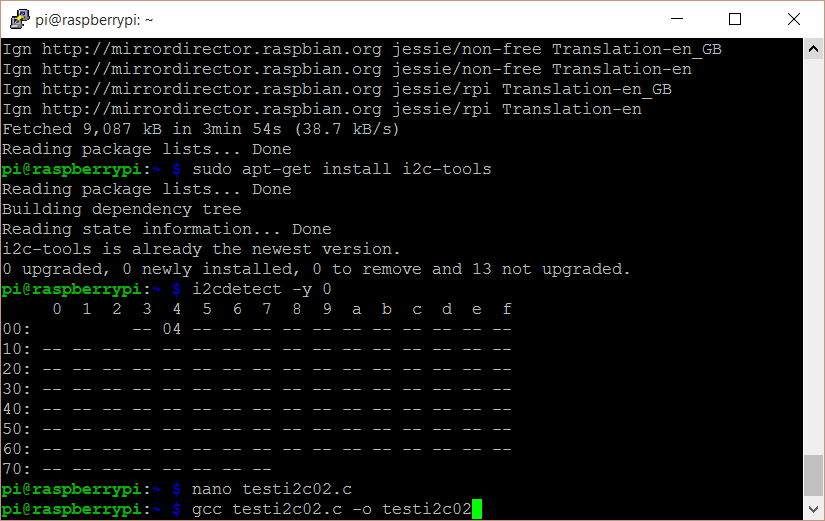
- Compile the application
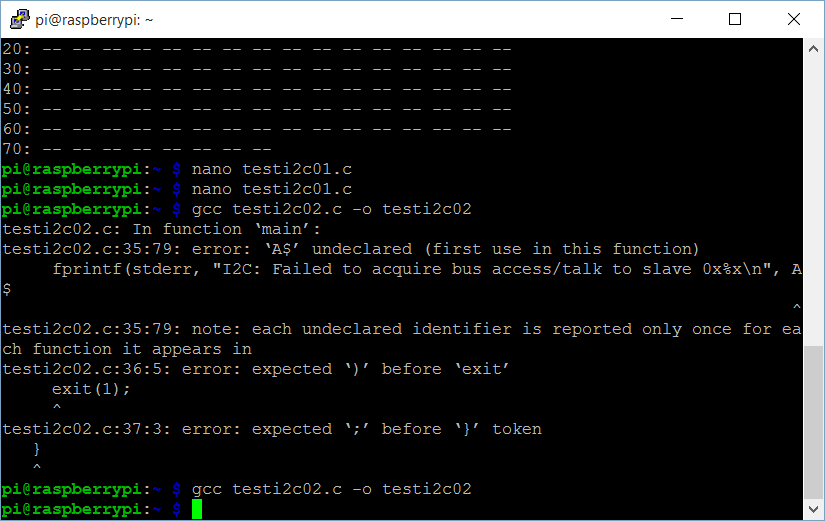
gcc testi2c02.c -o testi2c02

If you do see errors, go back and edit the file to correct them.
Once the changes are made, recompile and if you do not see any error messages, you are good to go.

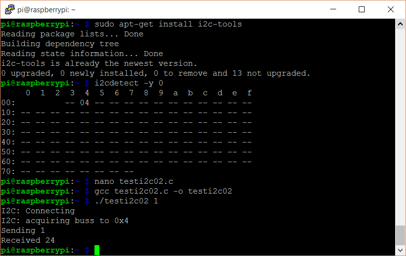
- Run the application
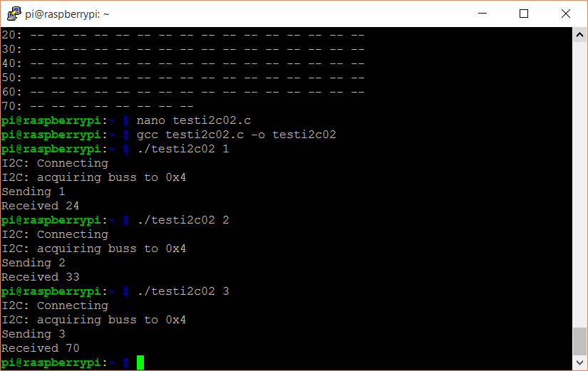
./testi2c02 1 {Gets the temperature in Celsius}

./testi2c02 2 {Gets the relative humidity in percent}

./testi2c02 3 {Gets the light level}

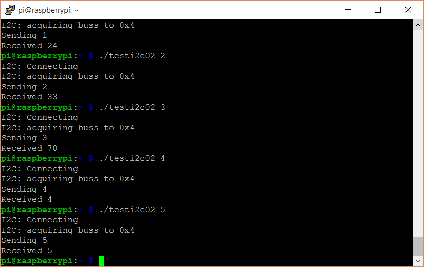
./testi2c02 4 {Turns the LED On}

./testi2c02 5 {Turns the LED Off}

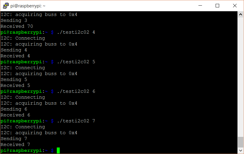
./testi2c02 6 {Flashes the LED when reading sensors. This is the default behavior of the LED}

./testi2c02 7 {Echos the number 7. This may be repeated with any other number up to 255}

…


That’s all for the day. Next I plan to try to send strings and develop a format for messages.