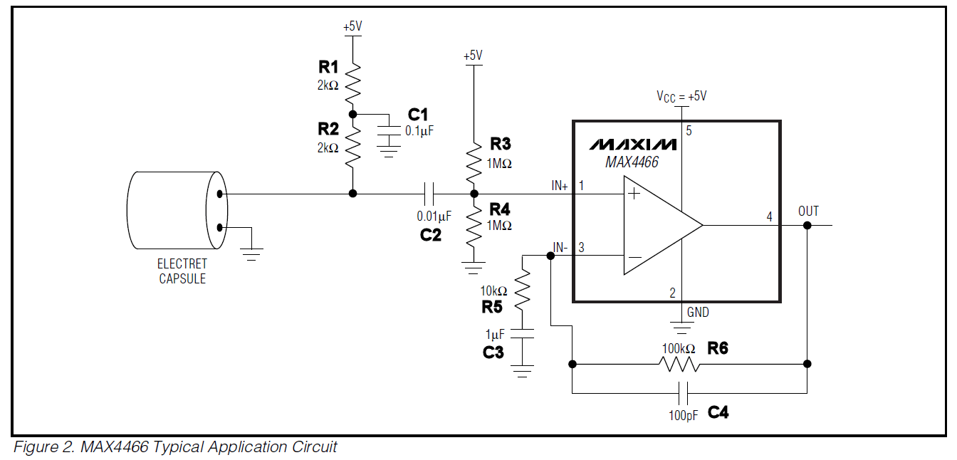
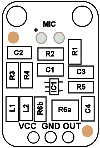
I purchased Adafruit’s Electret Microphone Amplifier – MAX4466 with Adjustable Gain (1063) and wanted to incorporate the circuit into a board that I am making to make a sound responsive decorative light. I saw a post from Adafruit that stated that the schematic was taken directly from the datasheet however looking at the component values on the board, it was obvious that some values had been changed. After a bit of reverse engineering of the board, it was confirmed that the schematic is indeed Figure 2 from the datasheet.
Component Listing (Note Capacitor Values taken from Datasheet Schematic and not verified)
-
-
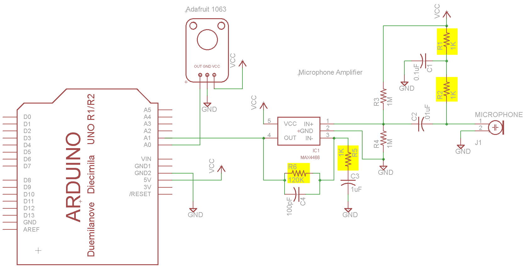
- IC1 – MAX4466
- R1 – 1KΩ
- R2 – 1KΩ
- R3 – 1MΩ
- R4 – 1MΩ
- R5 – 1KΩ
- R6a – 100KΩ
- R6b – 22KΩ
- C1 – 0.1µF
- C2 – 0.01µF
- C3 – 1µF
- C4 – 100pF
- L1 – Ferrite Bead
- L2 – Ferrite Bead
-
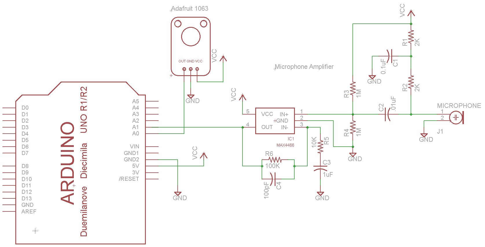
I wrote a simple program on the Arduino to capture 100 points of data per second for one minute and write the results to the serial output.
// Based on the Adafruit Trinket Sound-Reactive LED Color Organ
// http://learn.adafruit.com/trinket-sound-reactive-led-color-organ/code

#define MIC0_PIN 0 // Microphone is attached to Trinket GPIO #2/Gemma D2 (A1)
#define MIC1_PIN 1 // Microphone is attached to Trinket GPIO #2/Gemma D2 (A1)
#define DC_OFFSET 0 // DC offset in mic signal - if unusure, leave 0
#define NOISE 30 // Noise/hum/interference in mic signal
#define SAMPLES 60 // Length of buffer for dynamic level adjustment

int pointsPerSecond=100;
int captureMinutes = 1;
int delayMS = 1000/pointsPerSecond;
int datapoints=pointsPerSecond * captureMinutes * 60;
int curIdx=0;

void setup() {
 // put your setup code here, to run once:
 Serial.begin(57600);
 while (!Serial) {
 ; // wait for serial port to connect. Needed for Leonardo only
 }
 Serial.println(F("Idx\tAdaFruit\tMAX4466"));
}

void loop() {

 if(curIdx < datapoints)
 {
 // put your main code here, to run repeatedly:
 int adaFruitMic = analogRead(MIC0_PIN); // Raw reading from mic
 int max4466Mic = analogRead(MIC1_PIN); // Raw reading from mic

 Serial.print(curIdx);
 Serial.print(F("\t"));
 Serial.print(adaFruitMic);
 Serial.print(F("\t"));
 Serial.println(max4466Mic);

 curIdx++;
 delay(delayMS);
 if(curIdx >= datapoints)
 Serial.println("End of Sample");
 }
}
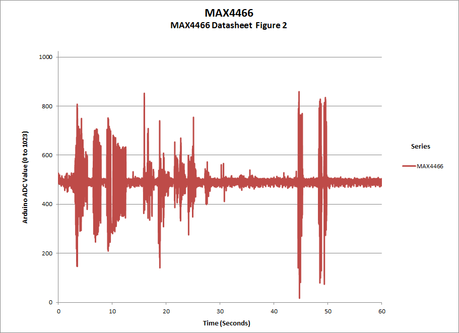
Here is the circuit diagram for the first test with values from the datasheet.
At first, I tried to use the values from the datasheet and noticed that the gain was not as high as the Adafruit module.
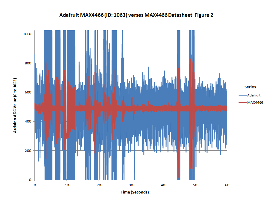
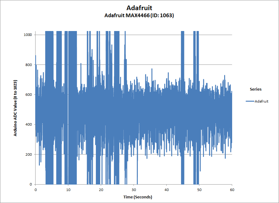
Modified values to be close to the values used by the Adafruit 1063 module. The results showed that the gain was much better so these values will be good enough for my application, If you need to use this for a different application where you need better performance, you may want to look into the RC values. By modifying the capacitor values, it may be possible to achieve a cleaner output.
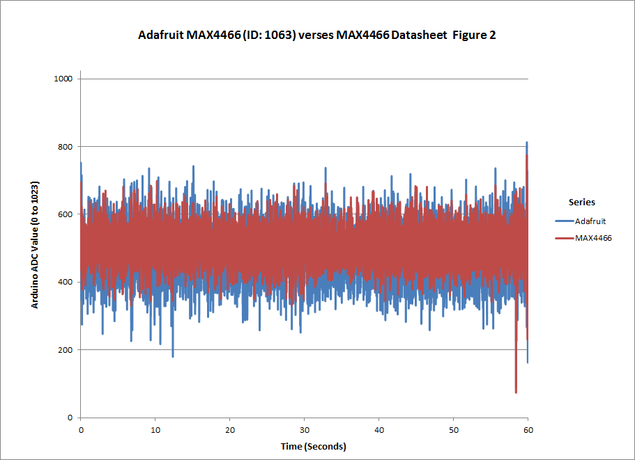
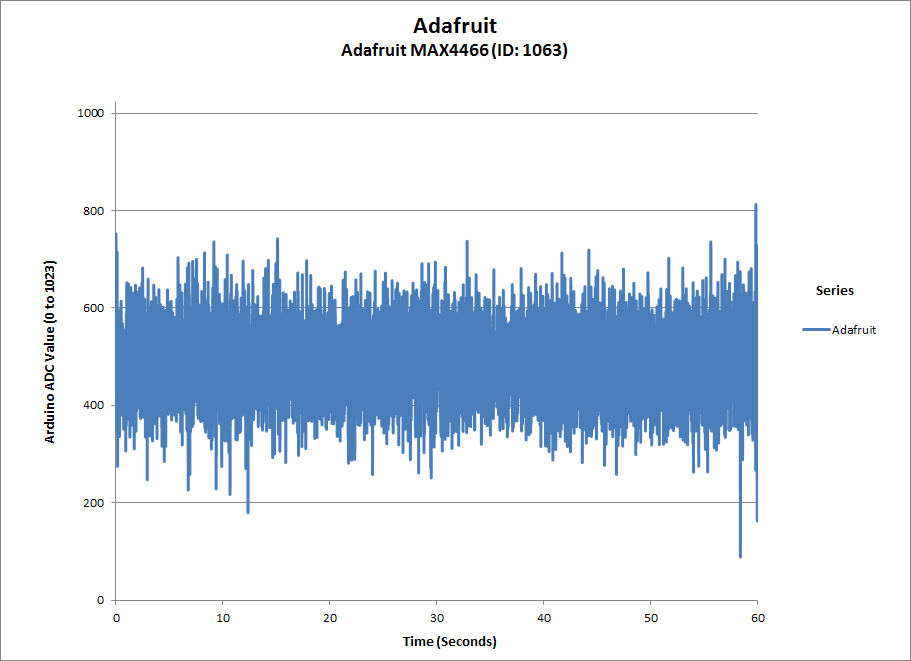
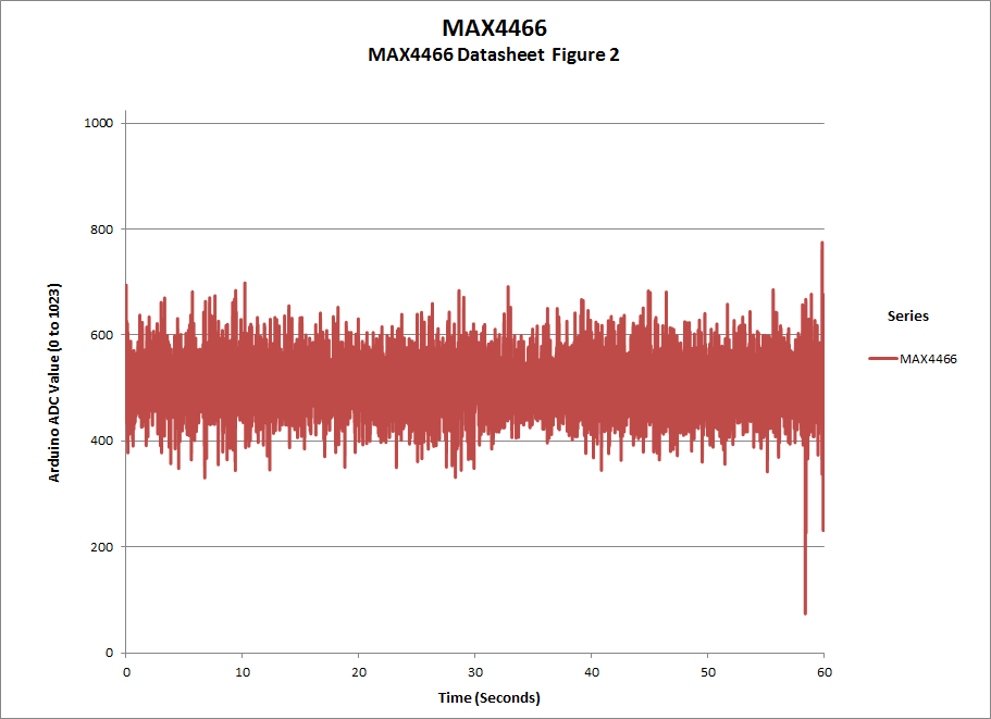
This is not a thorough analysis of the performance of these two circuits but as stated above, it was good enough to give me the performance that I needed. (Test with Datasheet Figure 2)
BTW: The values read by the Arduino ADC are between 0 and 1023. The signal is centered around 511 and has a noise level of ±50.
FYI: The gain for the circuit may be calculated as:
Gain = Rf/Rin = R6/R5 = 100KΩ/10KΩ = 10 (Dtasheet Circuit)
Gain = Rf/Rin = R6/R5 = 120KΩ/1KΩ = 120 (Modified Circuit)
You can also see from the graphs that the amplifier is driven to saturation. For my application that is acceptable but it may not be acceptable for your application particularly if you are creating a purely audio application.
10 replies on “A look at Adafruit’s Electret Microphone Amplifier – MAX4466 with Adjustable Gain (1063)”
Would you be able to replicate the results using a unidirectional mic and this same schematic?
Sorry, I do not plan to get back to this unless I have another project where I need to look at this again. You should be able to do the same if you have a unidirectional mic and the components to build the circuit(s). The graphs were made in Excel using the data returned from serial output of the Arduino code.
Man you made my day! I could not have dreamt a better post on presenting the Adafruit circuitry, most of all compared with a custom implementation, like I am trying to make one. Your mesures helped me understand the Adafruit component’s output and how to use it! Great job! (I will quote you I my next post as soon as I have time to write it ;))
Great article and you pointed out failings and benefits for other applications, great for novice like myself.thanks
Great article thank you very much – i was wondering why my max4466 circuit was so quiet.
One question though – you did not elaborate on what the ferrite beads were doing – i know it’s pretty standard to place one in series with Vcc, but there were two in the adafruit board – could you tell me how they are laid out in the circuit? I’m wondering if they’re in series with vcc but 2 types of beads in parallel ?
Similarly i noticed there’s two R6 values; is there just the adjustable resistor R6 and a passive resistor so that when the trimmer is at 0, there’s still some resistance in the circuit (i.e. R6 combined is never effectively 0)?
Are you sure the trimpot is 500K ohms? Reason I ask is this file says it’s 100K at line 4571.
https://github.com/adafruit/Adafruit-MAX4466-Electret-Mic-Amplifier-PCBs/blob/master/Adafruit%20MAX4466%20Mic%20Amp.sch
Not certain as it has been awhile since this post. I did pull out the mic amp and attempted to read the resistance of the trimpot. I was getting 250 ohms which matches neither value. I also took a look at the markings on the trimpot and I found a “5” and a “1”. That would make it appear to be 50 or 100,000 ohms. Since it is difficult to measure a resistor value in circuit and added to that is that it an smd component with extremely small pads, I have no faith in the value I measured. Based on the Adafruit schematic you referenced, which was not available when the post was written, and the referenced Maxim schematic, I have to assume that 100K is the correct value.
Thank you for pointing this out.