
Source Files are located on GitHub at https://github.com/richteel/pi_status.
The inspiration for this project is from a UCTRONICS Pi Rack that Jeff Geerling reviewed on his YouTube channel. The UTRONICS product may be seen at https://www.uctronics.com/cluster-and-rack-mount/for-raspberry-pi/1u-rack-mount/uctronics-pi-rack-pro-for-raspberry-pi-4b-19-1u-rack-mount-support-for-4-2-5-ssds.html. While I cannot build something as elegant as the UCTRONICS Pi Rack, I wanted to do something similar. I had a 1U ABS 19″ Rack Mount Case, so I decided to replicate the UCTRONICS product. Below is some information on my build.
Materials
- 19″ ABS Rackmount Case
- Quantity: 1
- Source: MPJA.COM
- Product Page: https://www.mpja.com/Rack-Mount-Case-ABS-Plastic-1U/productinfo/17086+BX/
- Draftboard 12″ x 20″ x 1/8″ for mounting plate
- Quantity: 1
- Source: Glowforge
- Product Page: https://shop.glowforge.com/collections/draftboard/products/draftboard
- Clear Cast Acrylic Sheet 12″ x 24″ x 1/16″
- Quantity: 1
- Source: Inventables (23876-15)
- Product Page: https://www.inventables.com/technologies/clear-acrylic-sheet-cast
- SD1306 128×64 pixel – I2C OLED Display
- Quantity: 4
- Source: Amazon
- Product Page: https://smile.amazon.com/Frienda-Display-Self-Luminous-Compatible-Raspberry/dp/B08RYSVG5Y/
- Lighted Momentary Switch (Normally Open (NO))
- Quantity: 4
- Source: Amazon
- Product Page: https://smile.amazon.com/gp/product/B09JLG7T98/
- 220 Ohm Resistor
- Quantity: 4
- Source: Amazon
- Product Page: https://smile.amazon.com/Projects-100EP514220R-220-Resistors-Pack/dp/B0185FGNWK/
- Micro SD to Micro SD Card Extension Cable
- Quantity: 4
- Source: Amazon
- Product Page: https://smile.amazon.com/gp/product/B07WWVBK8V/
- Raspberry Pi 4
- Quantity: 4
- Source: PiShop.us
- Product Page: https://www.pishop.us/product/raspberry-pi-4-model-b-1gb/
- 2.54mm Double Row Male Header
- Quantity: 4 (2×7 pins ea)
- Source: Amazon
- Product Page: https://smile.amazon.com/uxcell-Straight-Connector-Arduino-Prototype/dp/B07DJYFGHX/
- M2.5 Hardware
- Quantity: 16 each
- M2.5*5+5mm Male-Female Standoffs
- M2.5*11+6mm Male-Female Standoffs
- M2.5*5mm Screws
- M2.5 Nuts
- Source: Amazon
- Product Page: https://smile.amazon.com/gp/product/B07KM5B3PT/
- Quantity: 16 each
- M2 Hardware
- Quantity: 16 each
- M2*4+3mm Male-Female Standoffs
- M2*4mm Screws
- M2 Nuts
- Source: Amazon
- Product Page: https://smile.amazon.com/gp/product/B078RY4WB6/
- Quantity: 16 each
- Screws to secure the mounting plate to case. I was able to use some standard PC case screws. I believe they were 6#32*6BM similar to the ones at https://www.amazon.com/QTEATAK-Computer-Standoffs-Motherboard-Graphics/dp/B093CWNSXC/ref=zg_bs_3012917011_sccl_2/146-3318023-2391064?pd_rd_i=B093CWNSXC&psc=1.
- (Recommended) MX1.25-4P Male & Female connectors
- Quantity: 4 each
- Source: Amazon
- Product Page: https://www.amazon.com/gp/product/B09F3TQS9V/
- (Optional) Raspberry Pi PoE+ HAT
- Quantity: 4
- Source: PiShop.us
- Product Page: https://www.pishop.us/product/raspberry-pi-poe-plus-hat/
- (Optional) SATA to USB Adapters
- Quantity: 1 to 4 (Having a difficult time fitting to case. Using one externally.)
- Source: Amazon
- Product Page: https://smile.amazon.com/gp/product/B00HJZJI84/
- (Optional) 2.5″ SSD
- Quantity: 1 to 4 (Having a difficult time fitting to case. Using one externally.)
- Source: Amazon
- Product Page: https://smile.amazon.com/SAMSUNG-500GB-Internal-MZ-77E500B-AM/dp/B08QBMD6P4/
- (Optional) M.2 NVME SSD Enclosure Adapter
- Quantity: 1 to 4 (Can only fit 3 in the case)
- Source: Amazon
- Product Page: https://smile.amazon.com/gp/product/B07MNFH1PX/
- (Optional) NVMe M.2 SSD
- Quantity: 1 to 4 (Can only fit 3 in the case)
- Source: Amazon
- Product Page: https://smile.amazon.com/gp/product/B082BWY2C2/
Notes
- Source and product pages are representative of items. Materials may be sourced from other vendors such as Adafruit, Digi-Key, Mouser, etc.
- Currently (October 2022), Raspberry Pi boards are difficult to source. The situation should improve shortly. It is recommended that you use Raspberry Pi boards that you currently have or wait until they are available at approved vendors such as PiShop.us, Adafruit, Digi-Key, SparkFun, etc. You may be able to get a Raspberry Pi 4 at Amazon but it will be nearly triple the retail price. Below is the Amazon listing for a Raspberry Pi 4 with 4GB of RAM at $149.90 verses the retail price of $55 US.

You may find official retailers with Raspberry Pi boards in stock by going to https://rpilocator.com/.
Tools and Prerequisites
- Laser Cutter or hand tools for cutting mounting and front plates
- Ethernet Switch/Hub with PoE capability if using PoE+ Hat. If you plan to use PoE, your switch must support the IEEE 802.3at standard. (See Jeff Geerling’s video Review: Raspberry Pi’s new PoE+ HAT)
Laser Cutting Files
Download the files from GitHub at https://github.com/richteel/pi_status.
There are two files located in the case folder for use with a laser cutter. The front panel will be having some changes shortly so be warned if you decide to use it that it will not fit properly. I had only 1/8″ material so it is smaller to fit the case for testing. I now have 1/16″ stock and will be modifying the file for the 1/16″ material to fit properly in the case. I will also modify the notch for the USB to SATA adapter cable. I’m considering running them on top of the mounting plate rather than under it as it is not a good fit. If I do that, I may move the SD Card slot back to the center to avoid running it over a mounting hole.
The base was made with 1/8″ draftboard. The outline for the Raspberry Pi’s were scored while the rest was cut.


Assembly
The following directions utilize an unsupported method for mounting the PoE Hat. The PoE Hat should be mounted with the provided 10mm standoffs to provide a solid connection to the Raspberry Pi. Using the 11mm standoffs reduces the mating area but provides more contact area to allow a male header to make connection with the GPIO pins through the top of the PoE Hat. If you have a 2U case, it would be best to utilize the recommended 4 & 40 Pin Extra Tall Header (Push Fit Version) – POE HAT Set and a perfboard to make the GPIO connections. I attempted this setup but was unable to make it fit in the 1U case. That explains why UCTRONICS uses pogo pins on the bottom of the Raspberry Pi to make the GPIO Connections.
- Once the mounting and front plates are cut, the assembly may begin. The M2.5*5+5mm Male-Female Standoffs are secured to the mounting plate with M2.5 nuts for the Raspberry Pi mounts.
- The plastic housings for the Micro SD to Micro SD Card Extension Cables are removed and are secured to the mounting plate with the double sided tape provided. Make certain to line them up with the front plate and make certain that they are flush or extend slightly from the front plate.
- Once the standoffs and Micro SD Card Extension Cables are mounted, secure the mounting plate to the case with the 6#32*6BM or similar screws. You will not be able to put a screw under the second Raspberry Pi from the right as the Micro SD Extension Cable passes over the mounting point. I did not place any screws under either Raspberry Pi.
- Secure the Raspberry Pi boards to the mounting plate with the M2.5*11+6mm Male-Female Standoffs.
- Plug the Raspberry Pi PoE+ HATs into each Raspberry Pi and secure with the M2.5*5mm Screws.
- Secure the M2*4+3mm Male-Female Standoffs to the front plate with the M2*4mm Screws for mounting the displays.
- It is recommended to use MX1.25-4P Male & Female connectors to connect the switches to the 2×7 Header as the switches cannot be removed easily if not used. If you will not use the connectors, mount the switches to the front panel.
Solder wires to the push-button switches. - Solder wires to the OLED displays.
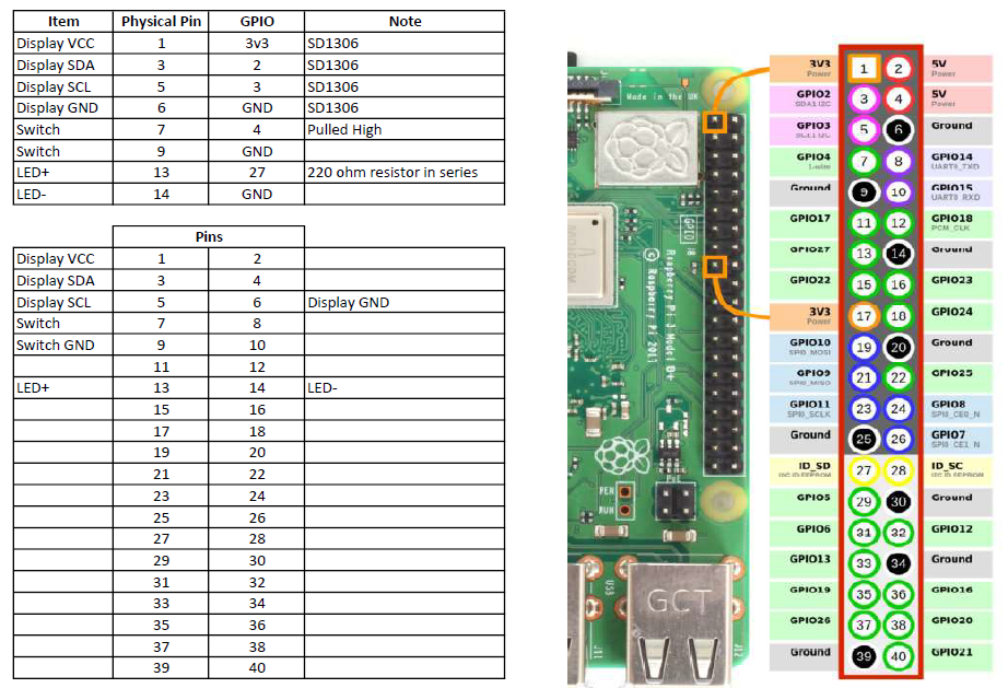
- Solder the wires to the 2×7 2.54mm Double Row Male Header. Refer to the diagram below. It is recommended to use a perfboard or heat-shrink to prevent accidental shorts.
- Once all the wires are soldered, mount the displays on the front panel with the M2 Nuts.
- Mount the push-button switches and plug the switches into the connectors if the connectors were used.
- Mount the front panel into the case.
- Spread the 2×7 male header pins apart slightly to provide a better connection when inserting through the top of the PoE Hat.
- Carefully plug the 2×7 male header into the PoE Hat. Make certain that you pay attention to the orientation. It is easier if you place the inside row into the PoE Hat then work the outside row into the PoE Hat.
- Double check that all connections are correct and all the screws, nuts, and standoffs are tight.
- Do not close the case yet! You need to test each Raspberry Pi first as it is likely that one or more of the pins on the 2×7 header will not be making contact with the GPIO pins so you will need to spread some pins apart a bit more to make good contact. It is also possible that one or more PoE hats will not make good contact with the Pi so that the fan will not run when the Raspberry Pi gets hot. You will need to check that everything on all Raspberry Pi boards are working before closing up the case.
- Once everything is working, you may close the case.
Below are a few photos of the build.


Software Installation
Follow the steps in the README.md file in the GitHub repository to install the pi_status software on each Raspberry Pi.
Testing and Troubleshooting
No Power to the Raspberry Pi
- Check if the PoE Hat has power.
- Is the Red LED lit on the PoE Hat? – No
- Does the network switch provide PoE+ (IEEE 802.3at standard)?
- Is the switch port that the Raspberry Pi is connected to provide PoE+? (Some switches supply PoE+ to some but not all ports.)
- Try another ethernet cable to see if that is the problem. Make certain that there are 4 pairs in the cable as all 8 wires are needed for PoE.
- Is the Red LED lit on the PoE Hat? – Yes
- Attempt to reseat the PoE Hat.
- Unplug the 2×7 male header to see if there is a fault causing a short.
- Is the Red LED lit on the PoE Hat? – No
Raspberry Pi boots but the fan does not run when the Raspberry Pi is over 50C
- Attempt to reseat the PoE Hat.
- Unplug the 2×7 male header to see if there is a fault causing the issue.
Display does not work at all
- From a Terminal Window, connect to the Raspberry Pi and run i2cdetect to see if device 3c is found.
i2cdetect -y 1 - Device 3c is found – No
- Remove the 2×7 male header and spread apart the pins a bit more or if not all pins are spread apart the same, spread the pins that are closer together apart further until they are all spread apart the same distance. Most likely the issue will be with pins 1 through 6 so concentrate your effort on those pins.
- Check for cold/bad solder connections on the display lines.
- Device 3c is found – Yes
- Make certain that the script is running. Run the following command to get the pid of the running script. If no pid is returned, then the script is not running.
ps ax | grep ‘code.py’ | grep -v grep - If the script is not running, try to run it again.
sh /home/pi/pi_status/display/launcher.sh -v - Check the error log to see if any errors were logged.
cat /home/pi/pi_status/display/logs/error.txt
or
sudo tail -f /home/pi/pi_status/display/logs/error.txt
- Make certain that the script is running. Run the following command to get the pid of the running script. If no pid is returned, then the script is not running.
Display is garbled or stops working
- Most likely, the display wires are too close to the transformer on the PoE Hat. Move the display wires so they are not close to the transformer and restart the script.
- Double check that Display SDA is connected to the Raspberry Pi SDA and the Display SCL is connected to the Raspberry Pi SCL.
- Check for cold/bad solder connections on the display lines.
LED on the switch is not lit and/or switch does not shutdown the Raspberry Pi
- Remove the 2×7 male header and spread apart the pins a bit more or if not all pins are spread apart the same, spread the pins that are closer together apart further until they are all spread apart the same distance. Most likely the issue will be with pins 7 through 14 so concentrate your effort on those pins.
- Check for cold/bad solder connections on the switch wires.
- Make certain that the switch and LED are connected to the correct GPIO pins on the Raspberry Pi.
Going Further
Once everything is working as expected, you can set up the Raspberry Pi boards to boot from SSD instead of the Micro SD Card. Below is a list of high-level steps that I followed to boot from the SSD Drives.
Steps from https://www.tomshardware.com/reviews/raspberry-pi-headless-setup-how-to,6028.html to setup a headless Raspberry Pi.
Raspberry Pi Imager
- Choose OS button
- Select your OS (Pi 4)
- Raspberry Pi OS (other)
- Raspberry Pi OS (64-bit)
- Raspberry Pi OS (other)
- Select your OS (Pi 4)
- Choose Storage
- Click the settings button or hit CTRL + Shift + X to bring up the settings menu
- Set Hostname
- Enable SSH
- Set username and password
- Set Wi-Fi network SSID, password, & country
- Set Locale
- Click Save
- Choose Write
Enabling I2C & VNC
- Open SSH Session
- sudo raspi-config
- Select Interfacing Options
- Select I2C
- Turn on the option
- Select I2C
- Select Interfacing Options
- Select VNC
- Turn on the option, then exit
- Select VNC
- Select Interfacing Options
Steps from https://github.com/richteel/pi_status to setup the display and button.
Setup Display and Button
- Open SSH Session
- sudo apt-get update
- sudo apt-get upgrade
* May want to reboot if updates were applied that require reboot
- sudo pip3 install adafruit-blinka
- sudo pip3 install adafruit-circuitpython-ssd1306
- git clone https://github.com/richteel/pi_status.git
- sudo crontab -e
- Add the following line to the end of the file
@reboot sh /home/pi/pi_status/display/launcher.sh - Reboot to make certain that the script starts at boot
- sudo reboot now
Steps from https://www.tomshardware.com/how-to/boot-raspberry-pi-4-usb to boot from USB.
Allow booting from USB
- Boot Raspberry Pi from SD Card
- Open VNC to machine and use the SD Card Copier to copy SD Card to USB Drive
- Open SSH Session
- sudo raspi-config
- Select Advanced Options
- Select Boot Order
- Select USB Boot
- Select Boot Order
- Select Advanced Options
- Shutdown the Raspberry Pi
- sudo shutdown now
- Remove the SD Card and restart the Raspberry Pi
You must be logged in to post a comment.