I purchased a few things on eBay recently, including some ESP32s for $7.99 each from eBay seller, miniduino. I have not worked with the ESP32 but I know that it can work with the Arduino IDE and can run CircuitPython. I am familiar with the Arduino IDE so I wanted to get the ESP32 to work with the Arduino IDE so I can test them out and make certain that they work fine.
Doing a Google search on ESP32 and Arduino IDE returned many results which helped to get me going. The process for getting the ESP32 up and running is nearly the same as with the Teensy boards. The exception is that the Teensy boards have one nice executable to get things setup. The high-level steps to get ESP32 working with Arduino are the following.
- Install the latest Arduino IDE if you do not already have it installed. (https://www.arduino.cc/)
- Depending on your operating system, you may need to install the driver. I am running Windows 10 so I needed to install the driver for the Silicon Labs CP2102 from https://www.silabs.com/products/development-tools/software/usb-to-uart-bridge-vcp-drivers.
BTW: The boards that I purchased have no markings on the CP2102 chip. I fear that the chips are counterfeit or a lower grade chip. The first one I tested works so I’ll keep my fingers crossed. - Once the driver was installed, I needed install the Arduino libraries for the ESP32 by cloning the GitHub repository at https://github.com/espressif/arduino-esp32.
NOTE: A better way it to follow the “Installation instructions using Arduino IDE Boards Manager” instructions on the GitHub page. -
Program the ESP32 with the blink example.
- Load the blink example in the Arduino IDE and modify the example to use pin 2 for the led.
/*
  Blink
  Turns on an LED on for one second, then off for one second, repeatedly.

  This example code is in the public domain.
 */

// Pin 13 has an LED connected on most Arduino boards.
// Pin 11 has the LED on Teensy 2.0
// Pin 6  has the LED on Teensy++ 2.0
// Pin 13 has the LED on Teensy 3.0
// give it a name:
int led = 2;

// the setup routine runs once when you press reset:
void setup() {
  // initialize the digital pin as an output.
  pinMode(led, OUTPUT);
}

// the loop routine runs over and over again forever:
void loop() {
  digitalWrite(led, HIGH);   // turn the LED on (HIGH is the voltage level)
  delay(1000);               // wait for a second
  digitalWrite(led, LOW);    // turn the LED off by making the voltage LOW
  delay(1000);               // wait for a second
}
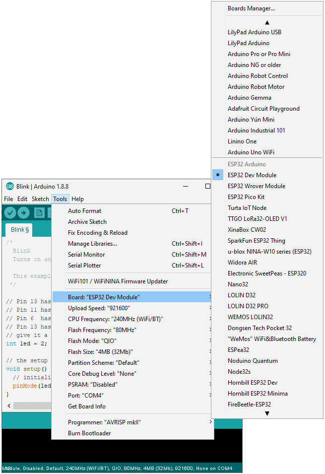
- Pick the “ESP32 Dev Module” from the “Boards” menu option

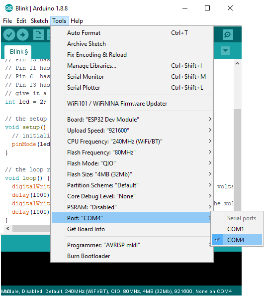
- Select the COM port for your board

- Upload the program to the ESP32 by clicking the upload button then press and hold the boot button on the ESP32 board. You may release the button once the upload starts.
You must be logged in to post a comment.